CAD+
There are various options for milling on both sides. The function was originally intended for moulding beddings. However, it has also proven itself for standardised inlays.
There are a few things to consider before construction. Not all inserts can be combined with every underside.
as some would overlap with each other. Of course, the question of sense must also be asked. If a somewhat experienced employee can finish sanding the underside in 3-5 minutes, does it make any sense at all to mill customised inserts where the shape of the underside is not known?
The following options are available:
- You can create a flat underside and mill the contour or outline to make it easier to place and mark an insole as before
- You can select a suitable underside for an inlay and then mill it
- You can create a parallel or modified surface from an existing inlay and use this as the underside
Re 1:
Any insole can be selected. Once the insole has been designed, go to CAD+ and select a flat insole. This can be customised in the dimensions or you can select a suitable size. Position the insole and you're done.
Alternatively, you can also create a flat underside from the insert (by clicking on "<< Library" while holding down the Ctrl key) and then adjust its dimensions.
Re 2:
For example, you select the insert 2001101 in size 40 and the matching underside (type 6) in CAD+, also in size 40. These surfaces are matched to each other and therefore fit together. Finished.
Re 3:
You select any insert and design it. Enter a material thickness of 5 mm throughout. Then go to CAD+ and click on "<< Library" while holding down the Shift key. This creates a parallel surface that is exactly 5 mm deeper than the original surface.
Of course, you can then adjust the material thickness of the inlay, but you should leave at least 3 mm thickness depending on the material hardness. Finished.
In GpMilling, double-sided orders differ in colour. They are slightly lighter in colour. Of course, these can also be milled as normal inserts. However, if you want to mill on both sides, you must activate the checkbox for bedding and enter the exact thickness of the material to be milled. You can see the minimum thickness in the milling job overview. Select the appropriate milling scripts and create the milling files. Two files are created (einlage.ncp and einlage_unten.ncp) These can then be milled. Always start with the underside. When selecting the material, make sure that the edges are straight. Otherwise correct positioning cannot be guaranteed. The underside is positioned on the right-hand side of the milling table, the top side on the left as usual. New routers from 2011 onwards should also have been measured correctly for this function. Older models should be checked before milling for the first time.
Error description
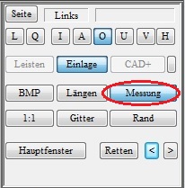
You would like to insert a measurement in a CAD module. If you are in a CAD module, there is a "Measurement" button in the toolbar at the top left, clicking on the button does nothing, or only the blue line in CAD is shown/hidden.
Troubleshooting
- Hold down the CTRL key and click with the left mouse button on the "Trade fairs" Button
- A dialogue appears in which you can select a measurement. Make sure you select a measurement that was taken with the correct measuring device (2D Scan, 3D Scan, KinectScan).
- The CAD measurement should then be used.
- If the desired measurement is not displayed in GP Manager version 6, make sure that "All data records" is selected.
Error description
After updating the operating system to Windows 10, an image is no longer displayed in CAD.
Causes of errors
Windows 10 requires the latest versions of DirectX and the graphics card drivers to function.
Troubleshooting
- Install the latest version of DirectX
- You can download the DirectX installation routine in the subfolder .\GpTools\Directx find. The setup file is called dxwebsetup.exe (How to find your GP Manager installation). You need Internet access for the installation to work.
- Run from the .\GpTools\Directx the individual Visual Studio Redistributable packages again (Vcredist_2008_SP1, Vcredist_2010, Vcredist_2013).
- Update the driver for your graphics card
Error description
After clicking on 1:1, the model is not displayed in the correct size on the monitor.
Causes of errors
The GP Manager is not calibrated for the monitor.
Troubleshooting
Version 7
- Start the GP Manager.
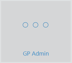
- Select "GP Admin“
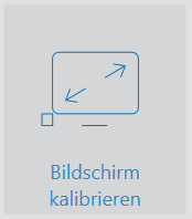
- Select "Calibrate screen“
- Drag the window at one corner so that it is displayed 10 x 10 cm on the monitor

Note:
If you use several monitor models, a 1:1 display is only guaranteed on the monitor on which the calibration was carried out. - Click on "Apply calibration„

Version 6.5
- Start the GP Manager.
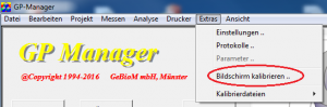
- Select "Extras" -> "Calibrate screen ...“
- Follow the points above from point 4.
