If you want to use a different tool for your router or replace a tool, there are a few things you need to bear in mind.
- ATTENTION:
Before installing the new tool, completely loosen the union nut of the chuck once. Clean the chuck and the motor shaft. Degrease the chuck and the tool with acetone before installation.
If the chuck is dirty, the tool may come loose. This can result in damage to the milling table. - After changing the tool, you must reset the zero point of the milling machine in the GP Manager. How you set the zero point depends on the type of milling machine you have. You can refer to Youtube For most milling machines, watch a video explaining how to set the zero point.
- In rare cases, you may want to use a tool with a different diameter. In this case, you must enter the diameter in the INI file for your milling cutter under ".\GpSystem\Fraese", the folder is a subfolder of the GP Manager (How to find your GP Manager installation).
- If you are not sure which milling machine to use, please also read "How can I recognise which type my milling machine has?„
- You must then recreate any existing milling files. The milling files still contain the old values for diameter and zero point. If you use these, the insert will not be milled correctly.
- When buying a tool, you should pay attention to the direction of rotation of the tool. If you purchase tools from us, you will always get the correct direction of rotation.
If this has not helped, you are welcome to contact GeBioM Support.

With MultiShore materials, there is often a desire to align the insoles not to the rear edge (outer edge of the material), which is standard with block materials, but to a transition line between the materials. GP InsoleFraese offers the option of defining such materials.

This allows insoles of different sizes to be aligned at the transition line. This ensures that the desired material is always in the forefoot.
To do this, the material must be measured and a new placement must be specified in the INI of the milling machine (e.g. GPM_320.ini):
[Bestueckung_1]
T_Name = MS-BlackOrange // Can be freely named
T_Orientation = HOCHKANT // Alignment of the inlays on the table
T_Stop = LEFT BOTTOM // The material is created here
B_Use_Multi_Auftrag = yes // MultiAuftrag (yes/no)
I_Anzahl_Boxen = 0 // For small blocks it makes sense to define several boxes
B_MultiShore = yes // Use Multi-Shore
I3_MultiShore_Dimension = 345 285 30 // Fixed size of the material Length x width x height
I2_MultiShore_Transition = 185/245 // Change material FROM / TO (from material rear)
I_MultiShore_Nullline = 200 // Zero line for positioning the inserts
I_MultiShore_Nulllinie_Prozent = 100 // % specification of the rearfoot (from the heel) with which the insole is positioned
T_Arrange = COLUMN // Determine whether the LINE or the COLUMN is filled first
Problem:
You design an inlay and reduce the material thickness very much because you want to have a thin/flat inlay.
After milling, however, you now realise that the insert is larger than the insert you designed.
Cause of the problem:
The milling head cuts out a rim around the insert. This edge is as wide as the circumference of the milling head.
In the following pictures you can see the same inlay milled twice. Once with a material thickness of 1mm (start and end of the insert are marked with a blue line) and once with a material thickness of 10mm. The difference becomes clear here


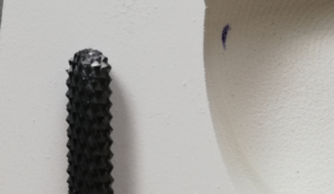
Problem solution:
Do not cut out the inlay directly on the edge of the milling block, but on the inside of the milling head.
Control option:
Design the inlay once with a higher material thickness and mill out this inlay once as a test. If the inlay fits this time, then you have simply cut out the inlay a little too generously.
If a single-pass milling machine suddenly stops during the milling process, there can be various reasons for this. Often, however, it is simply because the axis motors have to use too much energy to move the axes. This can be caused by a lack of lubrication, but also by a blunt milling cutter or a feed rate that is set too high. As the machine's control system has a current limiter for the axis motors, it issues an error message if the set value is exceeded.
If the milling process runs without milling material, this indicates one of the above-mentioned causes or a combination of these.
Therefore, check regularly whether the milling cutter is still sharp, the axes have sufficient lubrication and the feed rate is adapted to the hardness of the milling material.
To further reduce friction when driving the axles, it can help to rub a little oil into the sealing lips in which the axles are guided. The use of WD40 is not recommended, as this agent can penetrate into areas where it has a counterproductive effect due to its strong creeping properties and can cause faults that are difficult to locate.
Error description
The milling machine stands still or stops working after a while.
Cause of error
The computer's energy-saving mode interrupts the connection to the milling machine. As the router no longer receives any data, it stops. This error often occurs with milling machines that have a COM port if a COM-USB adapter is used to connect to the computer.
Troubleshooting
Decativise "Selective USB energy saving„
Error description
A microfuse in the iSM10 system module is defective and you would like to replace it.
Causes of errors
Fuses blow if there are strong fluctuations in the power supply or if an electronic component is defective.
Troubleshooting
Check whether the fuses in the module are still OK. If not, replace the defective fuses. You can find out how to find the fuses in the video below.
Error description
The GP Manager still displays the current milling jobs. However, it then crashes immediately.
Causes of errors
The GP Manager does not automatically delete old milling jobs. If there are too many completed jobs, the GP Manager can no longer create the list of completed milling jobs and crashes.
Troubleshooting
Rename the directory with the completed milling jobs and create a new directory.
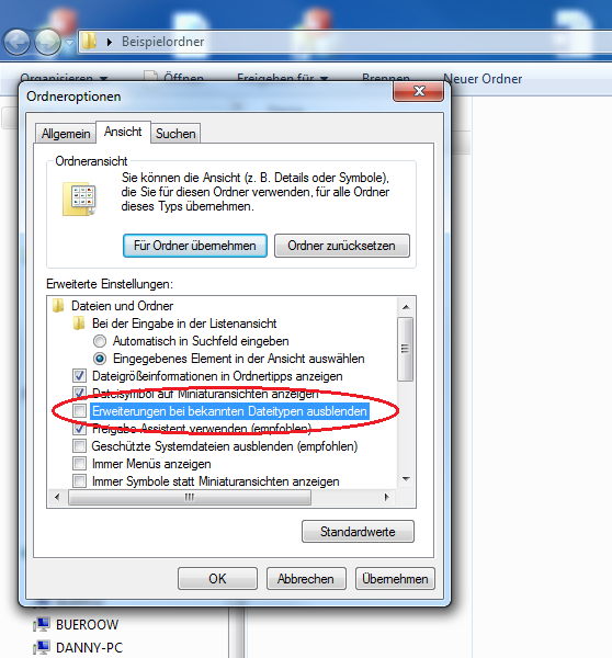
You can find the standard directory as follows:
- Make a Right click on the GP Manager link and select "Open file path„
- Open the folder .\GpData\Fraese\Inlays
- Name the folder Done um.
- Create a new folder with the name Done
In future, select the "Completed orders" and delete orders that are no longer required.
Identify milling type with the GP Manager
The easiest way to recognise the type of tiller is in the GP Manager. To do this, proceed as follows.
- Start the GP Manager.
- Select "Analysis" -> "GP milling machine„.

- You can read the type of milling machine you are using in the GP milling machine module.


Identify milling type by appearance
There are several router series, which differ at first glance in the colour of the housing.
turquoise: 100 series milling machines (GP M101, GP M102, GP M103)
blue: 200 and 400 series milling machines (GP M201, GP M202, as well as GP M401 and GP M401xxl)
grey: 300 series milling machines (GP M301, GP M302, GP M303)
red: milling machines of the 50 series (GP M151, GP M251)
100 series

All 100 series milling machines have a turquoise-coloured housing and are connected to an external computer via the COM port.
GP M101
These milling machines have a motor from Kress or Suna, the carbon brushes of these motors must be cleaned regularly. The computer is not integrated into the router and is connected with a COM cable.
GP M102/GP M103
Both milling machines have ISA750 motors, which are maintenance-free. The computer is integrated into the router. The GP M103 can be distinguished by the fact that it has two USB sockets and a switch at the bottom left (see picture below).

200 series
All milling machines in the 200 series have a blue housing.
GP M201
300 series
All 300 series milling machines have a grey housing. All milling machines are controlled via a COM port.

GP M301
The GP M301 is controlled using the GP Remote programme and connected to an external computer via a COM cable.
GP M302/GP M303
On both types of milling machine, the type plate is located at the bottom left of the milling machine (see picture below). The computer is integrated into the milling machine.

400 series
All 400 series routers have a blue housing. The difference between the GP M401 and the GP M401xxl is the size of the milling table.

GP M401
The milling table of the GP M401 is 1205 mm long.
GP M401xxl
The milling table of the GP M401xxl is 1600 mm long.
50 series
All 50 series routers have a red housing and the computer is integrated into the router. The easiest way to distinguish between the two routers is by the arrangement of the buttons on the front.
GP M151

GP M251

Error description
Instead of the new job, the milling machine mills the old job again and again. The milling machine does not accept new jobs.
Causes of errors
This is usually due to a network problem or an operating error in the GP Manager. Make sure that you have selected "Analysis" -> "GP milling machine" after you have selected the milling job also "Create milling file" select.
Troubleshooting
- Start the GP Manager
- Select the customer for whom you would like to create a milling order via "Project" -> "Determine", or create a new customer.
- Select the GP CAD file that you want to use for the milling machine by double-clicking on it.
- In the new view, select "Milling“

- You can set the settings for the milling job in the following dialogue. Click OK to write the milling file to the output folder.

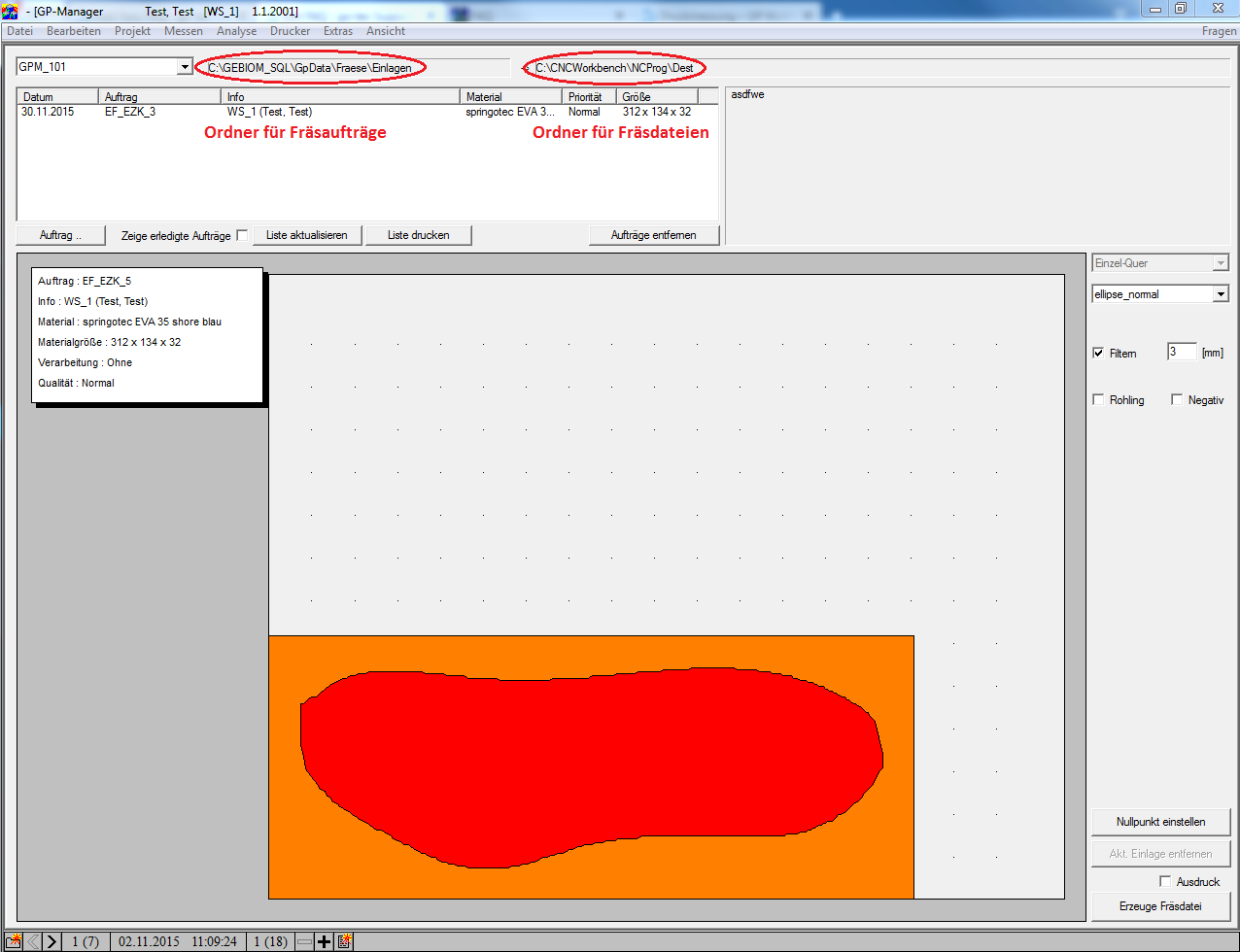
- Select "Analysis" -> "GP milling machine" the new order should be displayed here.
- Select the order by double-clicking on the date.
- Select "Create milling file„

- The file should now have been transferred to the milling machine. The job is now only orange, the buttons at the bottom right are no longer activated.

- To be on the safe side, manually check whether the GP Manager has also transferred the milling file to the milling machine.
- The paths at the top right under "Analysis" -> "GP milling machine" enter the folders for the Milling orders and the Milling files to.
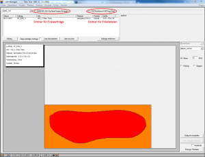
- Start CNC Remote and select "File" -> "Open" to check whether the path here matches the folder for the milling files. If the path is not identical, it is often the case that the GP milling machine writes the milling file to a temp folder. In this case, there is a network error.

- Make sure that the detailed view is activated in the following dialogue.

- Check whether the modification date corresponds to the time at which you created the milling file.
- Check whether the folder matches the folder configured in the GP tiller.


Error description
The brush on the router is so worn that it can no longer generate a sufficient vacuum and you want to change the brush yourself.
You need:
- 1 x 4 mm or 5 mm HSS drill bit
- 1 x replacement brush
- Pop rivets (4 mm) as well as matching washers and riveting pliers
- We strongly recommend riveting the new brush as well. The vibrations of the milling machine can cause nuts to come loose and fall into the milling machine. This can lead to damage to the tiller. If you still want to fasten the new brush with screws, do so at your own risk. In any case, make sure that you Self-locking nuts use. In addition, the screws should protrude as little as possible and have a countersunk head. You are responsible for any damage to the tiller caused by improper maintenance.
- 1 x hacksaw or heat gun
This is how it's done:
- Remove the brush cup from the tiller.
- Drill into the pop rivets from the outside. Take care to minimise damage to the brush pot when drilling.
- Cut the new brush into suitable pieces so that they fit into the brush head from the inside, or use a heat gun to mould the brush.
- Place the new brush in the brush pot and drill the corresponding holes in the brush.
- Place a washer around each pop rivet from the inside.
- Pull out the mandrel of the rivet with the riveting pliers until it breaks off.
Error description
When the tiller reaches the rest position, it immediately moves to the limit switch.
Cause of error
An incorrect value has been entered when determining the zero point.
Troubleshooting
If you have determined the value for the zero point in the GP Manager, you must enter it with a minus sign. If you have changed the zero point and then this error occurs, you have probably forgotten the minus sign in front of the value. The milling machine triggers the limit switch. This is how you set the zero point correctly:
- Follow the instructions for determining the zero point
- Ensure that the remote programme is started on the milling machine and that there is a network connection between the milling computer and the computer on which the GP Manager is installed.
- Start the GP Manager
- Select "Analysis"->"GP milling machine„
- Click on "Setting the zero point„
- Enter the correct zero point in the dialogue that opens in the remote program.
Error description
The remote programme displays the error message "Communication error no. 4 Timout when receiving a character".
Causes of errors
The error occurs if the programme cannot establish a connection to the milling machine.
Troubleshooting
The error often occurs because the remote programme has already been started. In this case, the second instance of the programme cannot access the milling machine.
- Make sure that the remote programme is only started once.
- Ensure that the milling machine is switched on.
- Ensure that the COM cable is connected to the router and the computer.
If you can rule out these errors, please contact customer support.
Error description
An error appears in the milling programme with the message Error 49.
Cause of error
The emergency stop switch on the milling machine was actuated. The system was then reset in the wrong order.
Troubleshooting
- Press the emergency stop switch on the milling machine again.
- First reset the emergency stop switch on the tiller by turning it.
- Reset the milling programme.