4.2 From the scan from GP FootMeasure3D to the gross moulding
1. open GP FussMess3D module & start measurement
On the start page of the GP Manager, click on the icon  start the module.
Once you have connected and switched on the 3D full-foot scanner, you can click on the ![]() to start the scanning process.
to start the scanning process.
If the scan is satisfactory, you can click on the ![]()
to exit the module and return to the GP Manager start page.
2. open GP CAD module & create new strips
On the start page of the GP Manager, click on the icon

start the module.
To create a new construction, please click on the button in the top right corner ![]() on. A window with your previous designs will then open. Click on the [New] button at the bottom of the window. Then activate the [Bars] button in the function box:
on. A window with your previous designs will then open. Click on the [New] button at the bottom of the window. Then activate the [Bars] button in the function box: ![]()
3. create mouldings from measurement
To generate a moulding from the 3D measurement, please click on the button [...]. ![]() Please select [Measurement] in the dialogue that now appears:
Please select [Measurement] in the dialogue that now appears: ![]() .
.
A window will then open showing all your measurements. Please select the measurement from the GP Foot Measurement 3D module here.
After you have selected a measurement, you will be shown this representation of the bar:
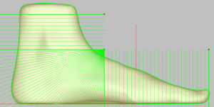
These green lines serve to delimit and break up the heel of the last. The upper line represents the upper cut edge of the last. The same applies to the toes. The line on the instep changes the resolution of the heel area. Here the point (as shown in the picture) should be placed close to the instep. You can move the dots with the mouse.
If these points are all set to your satisfaction, you can click on
![]()
create the mouldings. You can use the [Smooth] button below to smooth the moulding. However, please use the smoothing function with caution here, as the moulding will become smaller.
Click on the [Apply] button to return to the GP OptiCAD module with the moulding so that you can continue editing your moulding.
4. tip
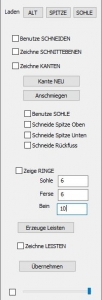
If you have created a moulding from a measurement, you can use this option to attach a tip to this moulding.
If you click on the [Tip] button in the "Load" area, the tip library opens. Here you can choose between the libraries "BIB_GP_Spitzen" and "BIB_GP_Spitzen_inSprengung" (here, the moulding is already in a specified blasting for boarding). Double-click on the desired point to add it to your design.
You can now adjust the tip on your moulding as follows:
Once you have selected a tip from one of the libraries, you can use the familiar combinations of the CTRL and SHIFT keys and the left mouse button to move it in different bar views and adjust it to the bars.
To edit and adjust the tip, tick the "Draw sectional plane" box. You can now define the area yourself at the corners of the two section planes (shown as triangles). When you have finished designing the cutting area, tick the "Use cutting" box. You can now define the transition between the cutting angles. If you like the transition, you can remove the tick next to "Draw cutting plane".
Use the slider at the bottom of this toolbox to set the transparency of the tip. To do this, the tick to the left of it must be set.
In the next step, tick the "Draw edge" box and click on the [New edge] button. The green line represents the end line and should always run below the red line.
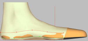
Click the [Adapt] button to adapt the edge to the mouldings.
Now you can set the edge step by step in all views (don't forget the view from below!).
By activating the "Use sole" option, the insole of the selected last is adopted.
If the foot being measured has a toe deformity, e.g. hammer toe, which would be equalised by the toe, you can tick the box next to "Cut toe top" or "Cut toe bottom". Such deformities of the measurement in the last are then adopted.
By activating the "Cutting back foot" option, you decide whether you want to retain the longitudinal arch of the last or the longitudinal arch of the measurement if it remains deactivated.
Once you have ticked the "Show rings" box, your moulding will be displayed like this:
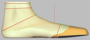
You can adjust the distance between the rings here
Click on the [Create moulding] button to display the finished moulding. If you are not satisfied with the result, you can remove the tick (which the system sets automatically after creating the moulding) and change the edge and rings for a better result. Then create the moulding again. Clicking on the [Apply] button completes this construction step and you can no longer change the tip and edges. Unless you reset the last "Save step". In "Tip" mode, the [Save] button has no function. After you have pressed [Apply], you can save this result and store it in the clipboard.
5. axes
Selecting the axes opens a selection box:

These 3 axes (bunion line, ankle axis and mechanical axis) are displayed on the measurement or on the last. These axis points can be moved and adjusted by grabbing the respective end of the axis with the left mouse button and editing them in the corresponding view, which can be changed in the process.
The mechanical axis represents the axis of rotation around which dorsiflexion and plantar flexion take place.
6. smoothing
Click on the "Smooth" option to open a selection box:

Use the "Global" option to smooth the entire moulding. Click on the [Execute] button in the selection box to perform normal smoothing. If you hold down the CTRL key while doing this, the smoothing is increased slightly. Pressing the SHIFT key will smooth the area strongly and pressing CTRL+SHIFT will smooth the area very strongly.
These key combinations in conjunction with the Execute button apply to all smoothing options!
Note: With the right mouse button, you can select several areas at the same time. You can also delete selected areas by selecting them again.
With the shape and surface options, you can specify exactly how and where you want to smooth your moulding.
Use the left mouse button to drag a rectangle over the area of the moulding that you want to smooth. You can set this rectangle in any bar view. The area to be smoothed is then displayed on the moulding:
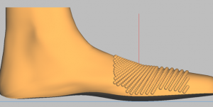
With the "Shape" option, a single unevenness is brought back to the height of the remaining moulding surface. The "Surface" option straightens several irregularities, i.e. a large uneven surface. These functions can be used both vertically and horizontally on the moulding.
The last two options "Erase" and "Fill" either remove (erase) or fill (fill) material in the selected area.
7. copy page
If you select the "Copy page" button, a mirrored copy of the displayed moulding is created. If a bar already exists for the other side, a dialogue box opens and you decide whether the existing bar should be replaced or not.
You can copy the moulding at any time. All models are also copied.
8. models
Models are pads, longitudinal arch recesses, etc. that can be positioned on the moulding. You can access the area for editing models by selecting the "Models" option in the main window of the toolbox.
Note: When milling the bedding, it may be advisable to position the models on the bedding. The models are displayed weaker over the mouldings in the bedding construction.

8.1 Insert models
To place a model on your moulding, select the "Models" option in the toolbox. You are then in the workspace for editing models. You can select models from the model library in the same way as you select a library moulding.

8.2 Position
Positioning is carried out using the following keyboard shortcuts.
Key combination Mouse movement Change
Ctrl key + left mouse button move horizontally right/left
Ctrl key + left mouse button to move vertically up/down
Shift key + left mouse button horizontal width/length (depending on view)
Shift key + left mouse button vertical height/length (depending on view)
8.3 Height
You can change the height of the activated model by entering a height in millimetres in the input field. The highest point of the model is adjusted to the specified height. The other dimensions of the model are retained.
![]()
Note: You can enter both positive and negative values for the height.
8.1.1 Embedding and transferring
Selected models are integrated into the interface after clicking the [Embed] button.
Attention: They are then part of the surface and can no longer be changed.
Selected models are integrated into the interface after clicking the [Apply] button, but can still be selected and edited afterwards.
Note: This can slow down the GP Manager. It is advisable to embed the models. Correct positioning must be ensured before embedding.
9. moulds
Depending on the selected shape, different modelling options are available to you. The options available to you can be found in the description of the individual moulds (see below).

After selecting one of the options "Sole", "Surface", "Hallux", "Base V", "Inner" & "Outer Ankle", the last is brought into the view in which the respective location is best visible.
The area to be modelled must now be defined and modelled. This is done by:
1) Draw a rectangle to define the effective range. To do this, place the
mouse pointer to the starting point of the rectangle and then move the mouse with
with the left mouse button pressed until the desired size is reached.
2) Place the centre (green rectangle) at the desired position on the bar by holding down the CTRL key and clicking the mouse.
3) Modelling the effective range by pressing the buttons o (top), u (bottom), i (inside), a (outside), v (front), h (rear). This causes the centre to move by 1 mm in the corresponding direction, whereby the reference of the change is always the slat. When moving, a view should be selected in which the change can be tracked.
In the effective range, the last is raised (or lowered) according to the following principle:
In the centre (green rectangle) to 100 %. At the edge of the effective range to 0 %.
The other points are calculated from the distance to the centre.
The changes can be tracked in the display on the workspace. The following two displays can be seen:
1) KO: 0 / 0 / 0 [mm] Display of the absolute change (origin in the
Intersection of the longitudinal axis of the foot and the line of the ball of the foot
2) Delta: 0 / 0 / 0 [mm] Display of the relative change
!!!Attention!!!: Modelling on the inner or outer ankle must always be carried out on the
groin and not on the leg!
9.1 Heel
After selecting the "Heel" radio button, the last is displayed in the "Outside" view.
Processing is carried out as follows:
| Key combination | Mouse position | Mouse movement | Focus of the change |
| Left mouse button +SHIFT | Heel | Horizontal | Entire heel
|
| Left mouse button +SHIFT | Heel comb | Horizontal | Heel comb |
| Left mouse button +SHIFT | Outermost heel point | Horizontal | Outermost heel point |
9.2 Pronation and supination
After clicking on "Pronation", the last is displayed in the "Outside" view, with "Supination" in the "Inside" view. The change is made as follows:
| Key combination | Mouse movement | Amendment |
| Left mouse button +CTRL | Top or bottom | Raise or lower laterally or medially |
The size of the change is displayed in mm in the workspace. If the moulding already has an increase as standard, this is displayed.
9.3 Inner edge and outer edge
After selecting the "Outside edge" radio button, the moulding is displayed in the "Outside" view, or in the "Inside" view for "Inside edge". Editing is carried out as follows:
1) Draw a rectangle to define the effective range. To do this, place the
mouse pointer to the starting point of the rectangle and then move the mouse with
with the left mouse button pressed until the desired size is reached.
2) Place the centre (green rectangle) in the desired position by holding down the CTRL key and clicking the mouse.
3) Elaboration of the scope of action:
| Key combination | Mouse movement | Amendment |
| Left mouse button +CTRL | Top or bottom | Raise or lower |
The moulding is retracted or extended in the effective area according to the following principle:
In the centre (green rectangle) to 100 %. At the edge of the effective range to 0 %.
The other points are calculated from the distance to the centre.
The changes can be tracked in the display on the workspace. The following two
Adverts can be seen:
1) KO: 0 / 0 / 0 [mm] Display of the absolute change (origin at the intersection of
Longitudinal foot axis and ball line)
2) Delta: 0 / 0 / 0 [mm] Display of the relative change
10. position

After selecting one of the options "Leg", "Heel", "Forefoot", "Sickle", "Split" and "Pointed foot", the last is brought into the view in which the respective location is best visible and the editing points are displayed.
You can adjust these points according to the selected area and move the moulding to the desired position. To do this, grab the respective editing point with the left mouse button and move it to the desired position while holding down the mouse button; the bar follows your mouse movements.
11th leg

If you want to build up the leg with a last (it does not matter whether it is a library leg last or from a measurement), you can do this here with several rings.
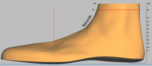
It is recommended not to build one large ring, but several small rings up to the desired leg height. Enter the top height of the last ring in the "Height" field. So if you have a last that is already 150 mm high and you want to build a 20 mm higher ring, enter "Height: 170" in the field and click on [New ring].
When customising the circumference, select a ring by clicking on it. You can now enter the desired circumference for this ring and confirm by clicking on the [Customise] button.
You can remove unevenness from the selected ring by clicking on the [Smooth] button. The selected ring is removed by clicking on the [Delete] button.
Note: The transitions between the rings can be adjusted using the green dots.