GP Opti CAD
Training video
- Introduction (0:23 min)
- Opening measurements (2:36 min)
- Axles and position (5:39 min)
- Attaching the tip (9:00 min)
- Smoothing (14:41 min)
- Dimensions (19:08 min)
- Forms (21:37 min)
- Models (23:47 min)
- Circumferential dimensions (24:42 in)
- Leg (26:35 min)
- Milling (27:27 min)
- Print (28:13 min)
Error description
GP Manager crashes without an error message when clicking on "Main window" or when switching to the start page. GP Manager may also crash when switching between different functions.
Cause of error
The latest versions of DirectX are not installed.
Troubleshooting
Install the latest version of DirectX.
You can download the DirectX installation routine from the support page:
-> Downloads -> Software -> GP Manager Installation -> DirectX -> dxwebsetup.exe
Once you have downloaded the application, please run it.
You will need Internet access for the installation to work.
Error description
You would like to insert a measurement in a CAD module. If you are in a CAD module, there is a "Measurement" button in the toolbar at the top left, clicking on the button does nothing, or only the blue line in CAD is shown/hidden.
Troubleshooting
- Hold down the CTRL key and click with the left mouse button on the "Trade fairs" Button
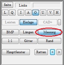
- A dialogue appears in which you can select a measurement. Make sure you select a measurement that was taken with the correct measuring device (2D Scan, 3D Scan, KinectScan).
- The CAD measurement should then be used.
- If the desired measurement is not displayed in GP Manager version 6, make sure that "All data records" is selected.
Error description
The insole/lasts are displayed in white in InsoleCAD/OptiCAD. Or you would like to adjust the colours in the InsoleCAD/OptiCAD display.
Cause of error
The settings have been changed or do not meet your requirements.
Troubleshooting
If you are using version 6.5:
- Start the GP Manager
- Select any customer
- Start the GP CAD module via the menu ("Analysis" -> "GP CAD")
- Then select "Extras" -> "Parameter ...„
- You can change the colour values here. If you select "Standard" the default value is restored
- In order for the values to be permanently adopted, you must click on the "-> INI" use!
- If this does not help either, select "Extended" -> "Standard“

Error description
After updating the operating system to Windows 10, an image is no longer displayed in CAD.
Causes of errors
Windows 10 requires the latest versions of DirectX and the graphics card drivers to function.
Troubleshooting
- Install the latest version of DirectX
- You can download the DirectX installation routine in the subfolder .\GpTools\Directx find. The setup file is called dxwebsetup.exe (How to find your GP Manager installation). You need Internet access for the installation to work.
- Run from the .\GpTools\Directx the individual Visual Studio Redistributable packages again (Vcredist_2008_SP1, Vcredist_2010, Vcredist_2013).
- Update the driver for your graphics card
Error description
After clicking on 1:1, the model is not displayed in the correct size on the monitor.
Causes of errors
The GP Manager is not calibrated for the monitor.
Troubleshooting
Version 7
- Start the GP Manager.
- Select "GP Admin“
- Select "Calibrate screen“
- Drag the window at one corner so that it is displayed 10 x 10 cm on the monitor

Note:
If you use several monitor models, a 1:1 display is only guaranteed on the monitor on which the calibration was carried out. - Click on "Apply calibration„
Version 6.5
Error description
When a point is attached to a last, there is always a transition. This means that there is a clear transition between the old last and the new tip in the form of a kink, a dent or a bump.
Causes of errors
Modelling a new tip requires some experience, as there are a few mistakes to avoid.
- The tip was pulled out too far after attachment.
- The cut surfaces were not set correctly.
Troubleshooting
- Start the GP Manager and select a customer
- Select the OptiCAD module
- Create a new data sheet
- Hold down the CTRL key and click on "Measurement„
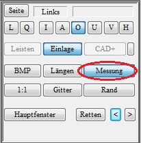
- Choose a plaster scan
- Select 3D

- Select "<< Library tips" and select a tip

- In the main window, select "Transparent" so that you can see the measurement through the tip. The conical surfaces result from the incorrectly positioned cut edges.
- You can extend the tip by holding down the CTRL + left mouse button. Switch through the views to get an impression of the 3-dimensional shape.
- Only extend the tip so far that the transition is not visible as a large bump; this is only clearly visible in the inside and outside views.
- You can then adjust the length of the tip with SHIFT + left mouse button.
- The tip can be rotated in the views using CTRL + Shift + left mouse button.
- Conical surfaces during processing can be ignored; these surfaces come from the non-optimised cut surfaces.
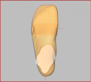
- Switch to the front view, deactivate "Transparent„, „Draw CUT" and "Draw KANTE". This view gives you an impression of whether the tip may still need to be rotated (CTRL + Shift + left mouse button). The tip should cover the plaster in this view.

- Then activate "Draw CUT" and "Draw KANTE" again, leave "Transparent" deactivated.
- The next step is to model the cut edges. To do this, select "Cut surfaces" from.

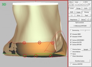
- The light blue lines should run along the widest part of the moulding. You can move the lines by dragging the ends while holding down the left mouse button.
- Change the views to get a spatial impression
- Distribute the dark blue lines as evenly as possible.
- The green lines indicate the lower cut surface.
- If you have set the cut surfaces correctly, the conical distortions (point 8) should have largely disappeared (see illustration above).
Error description
For example, you want to attach a tip to a plaster scan. To do this, you need to set the cut surfaces, but you will not see any cut edges
Troubleshooting
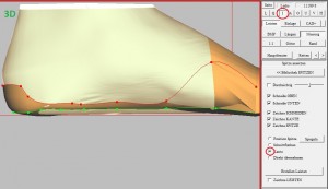
- In OptiCAD, select the settings from Figure 1
- The cut edges are displayed in this view.
- Remember to look at the cut edges in all views to get a spatial idea.
Error description
You want to change a last because your customer has a claw toe. This means that the last must be modelled at the site of the claw toe.
Troubleshooting
- Start the GP Manager and select a customer.
- Open OptiCAD
- Select the moulding you want to modify, make sure that Mouldings is selected. Then select in the main window "Moulds„
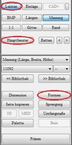
- In the main window, click on "Surface„

- Set the centre point (the highest point of the hammer toe) with CTRL + left mouse button. The green dot should then be at the corresponding position.

- Hold down the left mouse button and drag a frame around the centre point in the size of the shape to be modelled.

- You can reset both the frame and the centre point at any time. All changes remain in place.
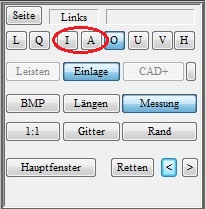
- Switch to view A (outside) or I (inside)

- You can model the shape using the o/u (up/down), i/a (inside/outside) and v/h (front/back) buttons. Each time you press the button, the shape is extended 1 mm in the corresponding direction.

- To judge the shape, change the view frequently or rotate the model with the mouse to get a spatial idea of the result.
Error description
Although the same moulding was chosen for both sides, the dimensions for the moulding on the two sides are different.
Causes of errors
There are two possibilities why the dimensions are different.
- The bale size on the sides was set differently
- The measurements of the two sides differ in length
Troubleshooting
GP OptiCAD calculates the size of the selected last based on the ball of the foot and the length of the measured foot. Depending on their value, the selected last is stretched or compressed accordingly. For this reason, the length specifications may differ. The decisive factor is that the last encloses the measured foot well. Different lengths of last are not an error in this case.
Error description
You have circumference measurements from a measurement (e.g. GipsScan) and would like to transfer the measurements to a skirting board. Alternatively, you have scanned a step foam and saved your measured dimensions with the measurement.
Troubleshooting
- Start OptiCAD and click with CTRL+left mouse button on "Measurement".
- Select the measurement you want to use in the following dialogue.
- You can now click on "Perimeter dimensions" click
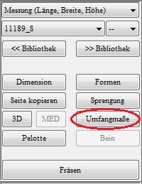
- Then select "Adopt dimensions from measurement“

- If you have set the lines for the ball, instep and heel measurements correctly in the measurement, the plantar circumference measurements will now run exactly around the last at the point where you measured.
Error description
There are no clear instructions on how to model a moulding. Is there a recommendation on the easiest way to model a moulding?
Troubleshooting
The toolbox main window in the CAD module is structured in such a way that it corresponds to our recommended working method. If you are modelling a moulding, we recommend working through the main window in the same way as you would read a book page.
Start with mouldings from the library
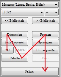
- They start at the top left with "Dimensions", and use the following buttons to work your way to "Models" through.
- Then proceed in exactly the same way for the buttons "Moulds" to "Leg“
- You can of course deviate from this method of working. For example, if you need both sides to be mirror-symmetrical, you can use "Copy page" at the very end as well.
Start only with 3D measurement
- If you do not want to use a moulding from the library, you can also start with a plaster scan from GP EasyScan 3D.
- Select a measurement with (CTRL + Measurement). In the following dialogue, select the measurement you want to use.

- You can then start modelling by selecting 3D.
- If you have added a tip to the plaster, select "Create mouldings", after which the journey to work is the same as for "Start with mouldings from the library„.
Error description
You are modelling a moulding and are in the 3D view in the main window. If you display the edges here, the lines may form loops.
Cause of error
The lines shown are a projection of a 3-dimensional line onto a 2-dimensional surface. The line does not intersect; the spatial course and the projection give the impression that the line intersects.
Troubleshooting
Always take a look at the other views as well. In the view of the bar from behind, you are only interested in the 6 points shown. You can edit these in this view.
If you switch to view I (inside), you can see how the lines run along the moulding.

