| 1 | Place the ramp on the prepared fixing holes. | 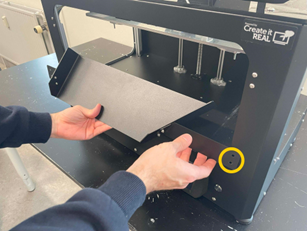 |
| 2 | Tighten the ramp with the four screws provided in the accessory bag. | 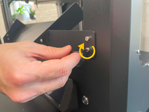 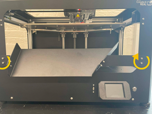 |
| 3 | Check that the ramp does not hinder the free movement of the print bed. To do this, use the button Z below in the option Manual control on the LCD screen. Using the screws that hold the main part of the ramp, you can adjust its position if necessary so that there is a gap of 3-4 mm between the edge of the ramp and the print bed. | 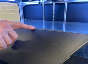 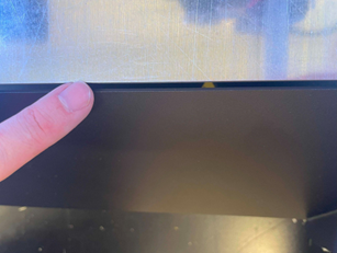 |
A camera is used to automatically start a print, which checks whether the object has been correctly removed from the printer and ensures that the print bed is free for the next print. Carry out the following steps to install this camera.
| 1 | Remove the 2 screws located on the left side of the top printer frame. | 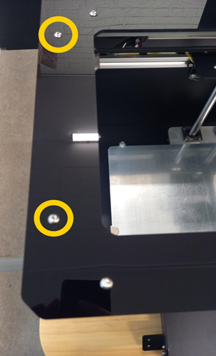 |
| 2 | Take the camera mount and the power supply unit. Place the power supply cable in the channel of the holder so that the power socket protrudes 6-7 cm. | 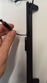 |
| 3 | Place the bracket on the left side of the upper printer frame, align the bracket with the holes of the removed screws and reinsert the fixing screws. When properly installed, the camera's power supply cable is concealed under the bracket. | 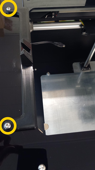 |
| 4 | Position the camera in the recess provided in the holder. |  |
| 5 | Connect the power cable to the camera. | 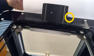 |
| 1 | Open the chamber and locate the cable inside. |  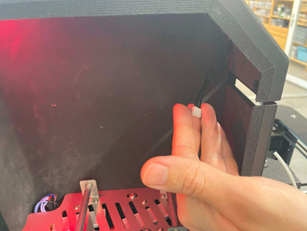 |
| 2 | Lay the cable out to the front and connect it to the sensor. | 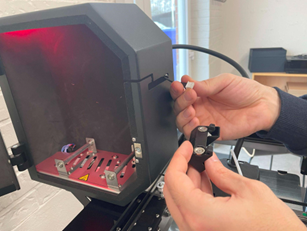 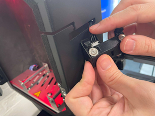 |
| 3 | Insert the sensor into the slot and pull it downwards. |  |
| 1 | Locate the 2 fixing holes for the print head cable holder on the back of the printer. | 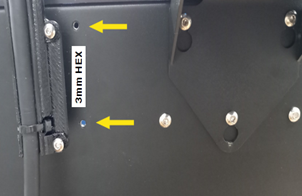 |
2 | Attach the bracket and tighten the screws using the 3 mm Allen key supplied. | 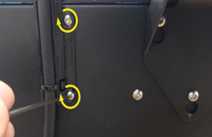 |
1 | Remove the adhesive tape holding the print surface to the print bed. | 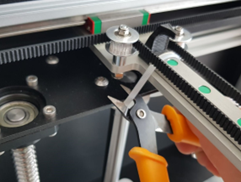 |
| 2 | Cut the cable tie that secures the ramp to the print bed for transport. | 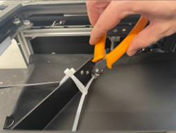 |
| 3 | Remove the ramp from the print bed. | 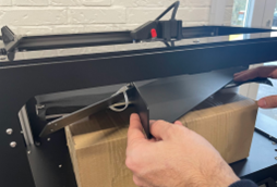 |
| 4 | Remove the black protective film from the surface of the print bed. | 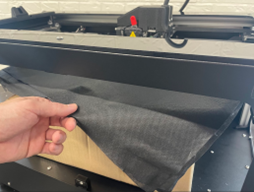 |
On top of the protective polystyrene you will find a small bag containing the printer parts.
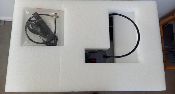
In the bag you will find:
- Filament tube
- Two small 1.5 mm thick plates
- Filament sensor for material escaping from filament box
- Cleaning filament
- 3mm hexagon spanner
- Power cable for the filament chamber
- Screws
- Cleaning brush for the nozzle
- AC power cable for the printer
- Power cable for the camera
- Mounting for the camera
- Camera

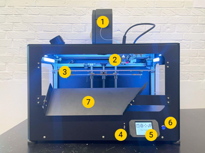
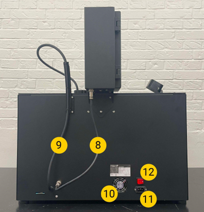
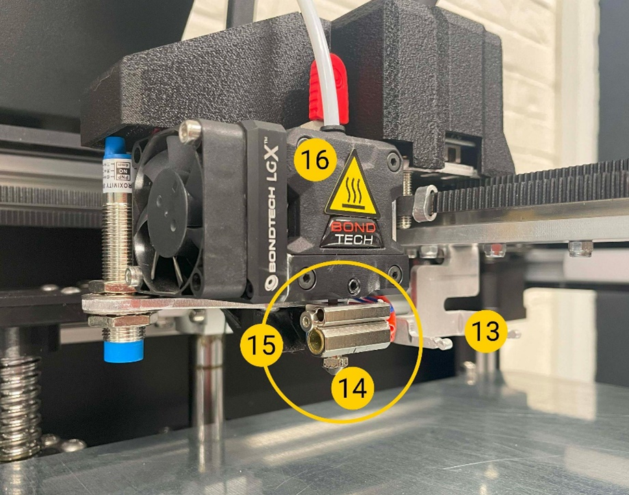
| 1-filament chamber For storing the filament used in the printer and to keep the moisture in the filament stable. 2 Print head For extrusion of the material. 3-Print bed Removable surface on which the object is printed. 4-USB connection For printing via a USB stick and updating the printer firmware. 5-LCD touchscreen To operate the printer. 6-On/Off switch Controls the printer's standby mode. 7-Ramp for removal 8-power cable for the filament chamber Cable that supplies the filament chamber with power. 9 Print head cable Power and data cable harness for the print head. 10-Exhaust fan To ventilate the electronics. 11 AC mains plug Input plug for the mains voltage. 12 Mains switch For controlling the flow of current to the internal power supply and the filament chamber. 13-Extraction fork 14-Nozzle 15-Hotend 16-extruder |
The 3D inlay printer Mike 2 with Upgrade 24/7 is a Fused Filament Fabrication (FFF) 3D printer. Its purpose is to print digital 3D models of insoles that are created in the software GP Manager InsoleCAD The process is designed to transform the moulds into physical objects (inserts) by depositing molten thermoplastic material (known as filament) layer by layer.
The printer has been specially designed to work with the filament Addigy® FPU 79AR8 of the company Covestro developed. Although the printer accepts other filaments (brand and/or material type), the use of these filaments does not provide optimal results and in some cases can lead to permanent damage to the machine.
Warning: Using filament that has not been authorised by the manufacturer/sales representative will invalidate the printer's warranty.

Manual
„CUBIX Pro“ with upgrade 24/7
3D printer inserts

GeBioM mbH
Wilhelm-Schickard-Straße 12
Germany - 48149 Münster
Phone +49 251 98724 - 0
Fax +49 251 98724 - 22
e-mail cubix@gebiom.de
www.gebiom.de