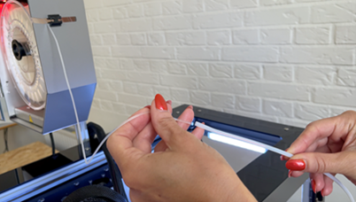
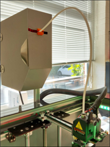
Before you start printing, a few things need to be checked.
- The print area is located on the print bed.
- The Print bed is empty.
Make sure that there is nothing on the print area (e.g. another printed object). - The print bed is clean.
If the printing surface is dirty (dust, grease, etc.), the extruded material will not adhere to the surface. Check that the surface is clean. Further information can be found in section 14.1. - Enough filament
Open the filament chamber and make sure that there is enough filament on the spool. - Clean nozzle
Material may stick to the nozzle of the print head from previous use. If this is the case, remove it with tweezers or the cleaning tool. Further information can be found in section 14.2
After the configuration file "wifi_config.cir" generated, place it in the root folder of an empty USB flash drive and carry out the following steps:
| 1 |
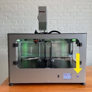
Switch on the printer
|
|
2 |
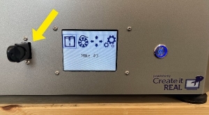
Connect the USB stick to the printer.
Important: The USB flash drive must be a FAT32 file format. |
|
3 |
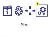
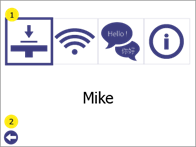
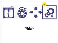
Open the menu Settings (1).
|
| 4 |
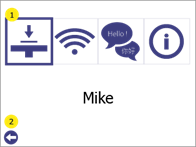
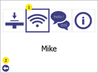
Select Wi-Fi configuration (1) from
|
|
5 |
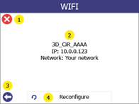
Select Reconfigure (4)
Display of the configuration of the printer in the network in (2). Press the cancel button (1) or the back button (2) to return to the main menu. |
|
6 |
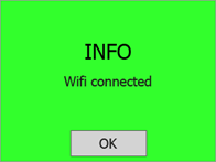
If successful, the confirmation message "Wi-Fi connected" will be displayed on the screen. At this point, the printer will be connected to the selected network and the printer name will be displayed on the printer's LCD screen. |
| 1 |
Open the GP Inlay Print module in the GP Manager.
|
|
2 |
Then click on the cogwheel in the top bar.
|
|
3 |
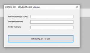
Fill in the fields: 1. the network to which you want to connect the printer (the printers only support 2.4 GHz networks).
2. the password for connecting to the network.
3. the printer name with which the printer is visible in the network.
4 Click on WiFi-Config.cir -> USB. A file with the name "wifi_config.cir" is now on the desktop. This is the configuration file required to configure the printer. |
Before you can also access your printer via Wi-Fi, it must first be configured.
NOTE: The following application must be installed on the computer in order to use the 3D print inserts module: Microsoft .NET Core Runtime 3.1.16 (x86). If this programme is not installed on your computer, please contact support.
The menu Print bed calibration offers the possibility to optimise the print bed position of the printer in order to achieve better adhesion (bonding) of the extruded material to the print surface.
Before you start this procedure, make sure that the temperature of the print head below 80 oC and the Nozzle is clean (see section 14).
| 1 | Open the menu Settings, by pressing the settings button (1).
|
|
2 |
Open the menu item Print bed calibration (1).
Press the Back button (2) to return to the main menu.
|
|
3 |
Open the menu Setting the print bed (1).
Warning! When you press (1), the print bed and the print head will move. Make sure that there are no objects or body parts in the print area.
Press the Back button (2) to return to the Settings to return. |
|
4 |
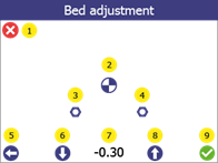
1. press the "Reference point" button (2). The print head moves to the reference point, takes a measurement and moves the print head and the print bed to its "zero" position. The offset value (7) for Mike v1 should be lie between -0.4 and - 1.2. If the measured value is outside this range, please contact support before proceeding.
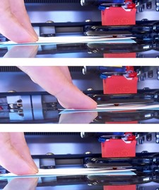
Note: (3) and (4) are calibration points that are used during maintenance. 2. take a piece of paper (normal printer paper, from a notepad, etc.) and carefully try to push the paper between the print head and the print bed. 3. if it does not fit (distance is too small), use the down arrow (6) to move the print bed downwards until the paper fits in between. 4. the paper is now between the print head and the print surface. Move the paper slightly back and forth while moving the bed upwards one step at a time using the arrow (8) (each step is 0.05 mm). 5. press the down arrow once (6). 6. confirm the new removal by clicking OK (9).
Press the cancel button (1) or the back button (5) to cancel the process (no changes are saved).
After this process, carry out a test print (see section 8.2) to confirm that the print bed calibration was successful.
|
A test pressure can be used to check whether the bed is correctly aligned. To do this, carry out the following steps:
| 1 |
Open the menu Settings, by pressing the settings button (1).
|
|
2 |
Open the menu Print bed calibration (1)
Press the Back button (2) to return to the main menu. |
| 3 |
Open the menu Test print (1)
Press the Back button (2) to return to the settings menu.
|
|
4 |
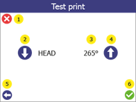
Select the print temperature of the print head for the test print. Change the target temperature (3) of the test pressure via the top (4) or bottom (2). If you use the standard filament Addigy® FPU 79AR8 is 265oC the correct value. Press the confirmation button (6) to start.
Press the cancel button (1) to go to the main menu. Press the Back button (5) to return to the Print bed calibration to return.
|
|
5 |
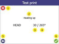
When the test print starts, the screen displays the status of the printer (2), the current temperature (3) and the target temperature (4).
Press the cancel button (1) to stop printing and go to the main menu. Press the Back button (5) to stop printing and go back one step.
|
|
6 |
Test print Successful
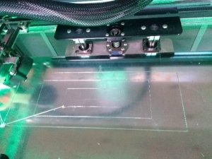
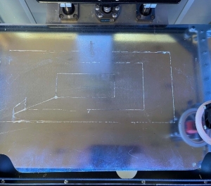
- 3 connected rectangles with evenly extruded lines. - Extruded filament is clear and transparent.
Test print failed - Uneven extrusion - Large parts without extrusion - Material stuck to the print head and not to the print bed.
If the test print fails, carry out the print bed calibration (see below).
|
It is an essential requirement of the 3D printing process that the print head is always at a constant distance from the print surface (print bed) when printing the bottom layer of the object.
If the gap is too large, the extruded material will not stick to the printing surface and will be pulled around by the head.
If the gap is too small (or the head and bed are touching), the material will not come out of the nozzle, which can lead to clogging. (The material will get stuck in the head and additional maintenance will be required to bring the printer back to an operational state).
The 3D printer Mike has an algorithm for correcting inaccuracies in the alignment of the print bed. However, it is sometimes necessary to adjust the reference height parameter (starting point) with the help of the user.
The process for changing the filament always takes place in 2 stages - removing the old filament and inserting the new filament. If the filament is being inserted for the first time (there is no filament to remove), simply go through the process as if filament is already included.
| 1 |
Open the menu Filament changeby pressing the filament change button (1)
|
|
2 |
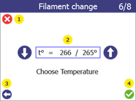
REMOVING THE OLD FILAMENTSelect the melting temperature of the installed filament (2) using the up and down arrows.
For the filament Addigy® FPU 79AR8 this temperature is 250-265°C.
Press the "Next" button (4) to go to the next step.
To cancel the process, press the cancel button (1). Press the Back button (3) to return to the Settings to return.
|
|
3 |
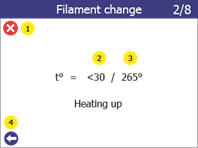
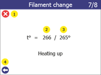
The printer starts to heat the print head to the selected target temperature.
The process continues automatically as soon as the target temperature is reached.
During heating, both the current temperature (2) and the target temperature (3) are displayed.
To cancel the process, press the cancel button (1). Press the Back button (4) to go back one step.
|
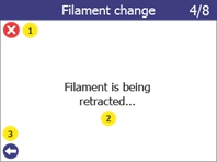
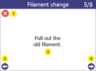
| 4 | When the target temperature is reached, the printer starts to remove the filament.
This starts with pulling back the filament in step 3/8 to ensure that no old filament remains in the nozzle and causes a blockage. As soon as the push-out is complete, the printer starts to remove the filament from the nozzle in step 4/8.
As soon as the filament has been withdrawn from the extruder, continue with step 5/8. Gently pull on the filament until the end comes out of the Teflon tube. The printer is now ready to remove the filament spool, either to replace it with a new spool or to store the filament.
Press the "Next" button (4) to go to the next step.
The current status of the procedure can be seen on the screen during the individual steps (2)
To cancel the process, press the cancel button (1). Use the Back button (3) to go back one step.
|
|
5 |
INTRODUCING THE NEW FILAMENTSelect the melting temperature of the new filament (2).
For the filament Addigy® FPU 79AR8 this temperature is 250-265°C.
Press the "Confirm" button (4) to go to the next step.
To cancel the process, press the cancel button (1). Use the Back button (3) to go back one step.
|
|
6 |
The printer starts to heat the print head to the selected target temperature.
The process continues automatically as soon as the target temperature is reached.
During heating, both the current temperature (2) and the target temperature (3) are displayed.
To cancel the process, press the cancel button (1). Press the Back button (4) to go back one step.
|
|
7 |
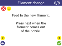
As soon as the printer has reached the target temperature, it starts automatically and attempts to extrude.
Insert the filament into the filament tube.
Push it down until the print head grabs it. Then release the filament and look at the lower end of the print head.
As soon as the print head starts to extrude the filament at a constant shape and speed, press the "Confirm" button (3)
Attach the filament tube to the print head and the filament chamber using the connector (see section 7.2.2)
The filament replacement process is now complete.
To cancel the process, press the cancel button (1). Use the Back button (2) to go back one step.
|
 Press the Back button (2) to return to the main menu.