By clicking on the "Milling" button, the error message "The insert has negative height values! It cannot be milled!"

This error message appears if a part of the insert is below the zero line. The easiest way to rectify this error is to specify a greater material thickness for the insert. You can access these settings from the standard work area of the main window via "Material thickness". Enter larger values here so that the deposit is above the zero line.
Make sure that the screen has been calibrated for 1:1 display. You can calibrate the screen in the GP Manager by selecting "GP Admin" -> "Calibrate screen", this is described in the GP Manager manual.

Attention: If you use different monitor models, make sure that you can only calibrate the settings for one monitor. If the monitors are not identical, it is not guaranteed that the 1:1 display is guaranteed on both monitors.

The input of customer data is only important for GP OptiCAD if the created moulding is to be manufactured by Spenlé.

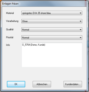
After clicking on "Milling", a dialogue box appears in which you can make additional settings (material, processing (surface), quality and priority) before producing or sending the insert data.

Fräsen-Dialog


Once all the entries have been made in the dialogue box, the dialogue box can be closed with "OK" can be closed. A file is then created which is used for further processing by the GP Fräse programme.

Note:  The entries in the list fields can be extended as required by the customer.

In the Material thickness work area, the material thickness can be specified for individual areas of the insert. The specifications are in millimetres, changes are made after clicking on the "Customise" button and displayed immediately.

Note:  The current values of the insert are displayed to the left of the input fields. The values are only displayed after clicking on the "Customise" has been changed. The numbers must be entered in English notation. This means that a full stop must be entered instead of a comma.

Arbeitsbereich-Materialstärke

Figure 32: The material thickness workspace

If a thickness is specified for the cover material, this value must be smaller than the smallest specified material thickness. This value is saved internally as soon as the material thickness area is exited.

Each click on the tip tray button adds 3 millimetres of tip edge.

The heel of the insole is raised or lowered to the centre in the selected area.

Placing the change area: The area is displayed in the "A" is released.
Setting the point of attackFree within the range with Ctrl + left mouse button.
Possible buttons: o and u.
Free rotation with Shift + left mouse button: yes

The heel edge of the sole is raised or lowered in the selected area.

Placing the change area: The area is displayed in the "A" or "I" is released.
Setting the point of attackFree within the range with Ctrl + left mouse button.
Possible buttons: o and u.
Free rotation with Shift + left mouse button: yes

The outer edge of the sole is raised or lowered in the selected area.

Placing the change area: The area is displayed in the "A" is released.
Setting the point of attackFree within the range with Ctrl + left mouse button.
Possible buttons: o and u.
Free rotation with Shift + left mouse button: yes

Attention: The function lowers/raises the entire insert up to the centre line. Excessive changes will result in a "kink" in the centre of the insert. The function should therefore only be used for changes up to a maximum of 3 mm!