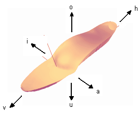
The inner edge of the sole is raised or lowered in the selected area.

Placing the change area: The area is displayed in the "I" is released.
Setting the point of attackFree within the range with Ctrl + left mouse button.
Possible buttons: o and u.
Free rotation with Shift + left mouse button: yes

Attention: The function lowers/raises the entire insert up to the centre line. Excessive changes will result in a "kink" in the centre of the insert. The function should therefore only be used for changes up to a maximum of 3 mm!

In the selected area, the inlay can be twisted sideways, upwards/downwards on the outside.

Placing the change area: The area is displayed in the "A" to the desired size from the front or back while holding down the left mouse button drawn.
Setting the point of attack: The point of attack is fixed.
Possible buttons: o and u.
Free rotation with Shift + left mouse buttonNo, only standard views via the buttons in the function box are possible.

In the selected area, the inlay can be turned upwards/downwards on the inside.

Placing the change area: The area is displayed in the "I" to the desired size from the front or back while holding down the left mouse button drawn.
Setting the point of attack: The point of attack is fixed.
Possible buttons: o and u.
Free rotation with Shift + left mouse buttonNo, only standard views via the buttons in the function box are possible.

The sole is moulded in the selected area.

Placing the change area: The area is displayed in the "O" is released.
Setting the point of attackFree within the range with Ctrl + left mouse button.
Possible buttons: i, a, o, u, v, and h.
Free rotation with Shift + left mouse button: yes

Depending on the selected shape, different modelling options are available to you. The options available to you can be found in the description of the individual shapes (see below).

Hauptfenster-formen


As a general rule: to deform an inlay, use the keyboard (see 3.5.4.7 Special). If you use the buttons (see illustration below), the selected point of action (green square) is moved one millimetre in the selected direction.

Bewegungsrichtungen


Direction button (see illustration above) Changes by 1 mm
Shift + direction key (see illustration above) Minor deformations
Ctrl + Shift + direction key (see illustration above) smallest deformations

While editing, you can change the model with Shift + left mouse button and a mouse movement to view the changes.

Arbeitsbereich-Formen

Figure 31: The mould workspace

To insert a sharp-edged model into the construction, proceed as follows.

First insert the desired model. Then enter a special character for the height, for example $, which will "destroy" the model. You can now assign the height you would like to the model (both positive and negative values). The model is then embedded with sharp edges.

scharfkantiges-Modell

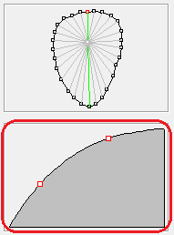
The slope of the selected line is shown in this view. If the line is enabled for editing, two additional points are displayed that can be moved with the mouse. Moving them changes the gradient.

Punktmodell-Bearbeitungsboxen-Anstiegsbox-markiert

Figure 30: The ascent view

In this box, you can mark the points of a selected point model with a simple mouse click. The rise of the line to the centre now appears in the rise view.
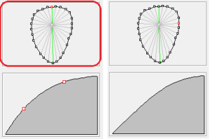
Abbildung_29

Figure 29: Left: The line selection box is outlined in red, the top point (red) is selected. The green line to the centre point is shown in the ascent view. Right: The right-hand point (red) is selected, the grey line to the centre point is shown in the ascent view. As the rise is between two green lines, it is calculated from the rise of both green lines.

By double-clicking on a point in the selection box, the grey line is coloured green and released for editing in the ascent view. Two red squares are now displayed in the ascent view. These represent points on the slope curve; the slope can be changed by moving them. The more lines you release for editing, the finer you can model your model. In practice, however, it has proven to be best to edit as few lines as possible. It is usually sufficient to edit 4-5 lines.

GP InsoleCAD calculates the rise for the grey lines between the green lines in such a way that there is a smooth transition from one modelled rise to the next modelled rise. You can see this if you mark the points between two green lines one after the other and observe the changes in the rise view.

NoteTo practise, find a point model and select a height for the model that is too high (e.g. 10 mm). You can then better observe the changes to the model in views A, I, H and V.

Key combination Amendment
Left mouse button Select a point and view the ascent
left double click Selection of a point and the ascent for editing

As described in section 3.5.4 Models, point models can be customised by changing individual points. The boundary points can be changed by using the 3.5.4.6 Shapes option. How to adjust the slope of a point model is described below.

NoteYou can manually adjust the gradient for each line of a point model. However, it is usually better to define 4-5 lines and have the transitions between them calculated.

The two boxes in the lower section of the toolbox are used for modelling point models.

Selected models are displayed after clicking on the "Embed in the surface" is integrated into the interface. When entering numbers, make sure that the English spelling is used. This means that a full stop must be used instead of a comma.

AttentionThey are then part of the surface and can no longer be changed.