You can change the height of the activated model by entering a height in millimetres in the input field. Then click on the button "Height". The highest point of the model is adjusted to the specified height. The other dimensions of the model are retained.

Werkzeugbox-Punktmodell-Höhe-markiert


NoteYou can enter both positive and negative values for the height.

If the option is activated, the styles are "added" to each other (style, on style, on style, ...). If the option is deactivated, the models are added to the insert surface and blended with each other.

Note: If you stack models on top of each other, it is advisable to start with the smallest model, as it is then easier to re-select!

Displays all models with a texture. However, you can still only edit a single model. You can recognise the active model as the highest point of the model is still displayed as a pink square.

The boxes are used to smooth the edges of the model when embedding it in the inlay.

You can use this function to edit any model (surface or point model). The function is identical to the function of the same name for insoles (see 3.5 3D modelling of insoles with GP InsoleCAD), but the operation is slightly different.

While holding down the left mouse button a rectangle around the area you want to change. You can then set the point of application of the deformation (green square) with Ctrl + left mouse button anywhere within the rectangle and drag with the mouse.

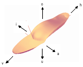
If you release the mouse button, you can move the point 1 millimetre in the specified direction using the V/H (front/back), I/A (inside/outside), O/U (top/bottom) buttons (see Fig. 28). Only the currently selected model is moulded. If changes smaller than 1 millimetre are required, the following key combinations are possible:

Direction button (see Figure 28) Changes by 1 mm
Shift + direction key (see Figure 28) Minor deformations
Ctrl + Shift + direction key (see Figure 28) smallest deformations
Bewegungsrichtungen

Figure 28: Keyboard shortcut and direction of movement

NoteThis function only has an effect on point models (see 3.5.4 Models). You must be in the standard view O (top) to use this function.

You can use this function to move individual points of point models on the workspace. This function has no effect on surface models.

Key combination Mouse movement Amendment
Ctrl key + left mouse button horizontal move right/left
Ctrl key + left mouse button Vertical move up/down

To place a model, use the option "Position" in the workspace "Models" of the toolbox. Positioning is done using the following keyboard shortcuts.

Werkzeugbox-Modelle-Funktionen-Position-markiert

Key combination Mouse movement Amendment
Ctrl key + left mouse button horizontal move right/left
Ctrl key + left mouse button Vertical move up/down
Shift key + left mouse button horizontal Width/length (depending on view)
Shift key + left mouse button Vertical Height/length (depending on view)

Some special functions of the model can be influenced via the details. These functions are not normally used and are therefore deactivated.

Among other things, models can be mirrored. When mirroring the models, ensure that they are mirrored at the coordinate origin (intersection of the bale line and foot axis).

Individual models can also be exported as STL files.

Modell-Eigenschaften-Details

To change the properties of a model, first select the model. You can then change the properties of the model in the Models workspace via "Properties ..." to customise the model.
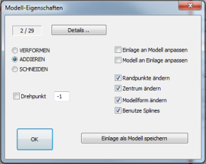
Modell-Eigenschaften

Figure 27: Properties of models

The value 2 / 29 indicates how many points the model consists of. The value cannot be changed.

Moulding: This option is obsolete and is no longer used.

Add: To be compared with gluing. The inlay is increased by the value of the model.

CuttingThe model remains on the zero line and only that part of the model which is higher than the insert influences it.

Pivot pointThis function only addresses some models from the library. This function can be used to define the centre of rotation of a CV model.

Adapt insert to modelIf you assign this property to a model and the model protrudes beyond the surface of the insert, the insert is adapted to the shape accordingly.

Adapt the model to the insoleOnly applies to special models under special circumstances.

Change edge pointsIf the check mark is set, you can change the edge points of a model.

Change centreIf the check mark is set, you can change the centre of a model.

Change model shapeIf the check mark is set, you can change the model shape/dimensions of a model.

Use splinesIf the check mark is set, the model shape is rounded. If the tick is not set, the models are sharp-edged. To illustrate this, it is best to view a model from the outside and select this property.

Note: These properties are also adopted when saving models. If you want to call up a basic model and permanently set a property, it is best to save the model again with the desired properties!

Saving and loading styles from the library works in a similar way as for inserts (see 3.4.1 Library management). However, no grading tables are required.