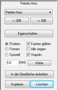
Models are pads, toe bridges, arches, etc. that can be positioned on the insole.
You can access the area for editing models by selecting the "Models" select.
In GP InsoleCAD A distinction is made between two types of model. On the one hand there are surface models and on the other point models. The biggest difference between the two model types is how these models can be edited and how the models are displayed in the software.
Surface models: This can be imagined as an inlay. The shape of the model can be edited using similar functions to those used to model the insert. This means that the model is changed by deforming it, as the model consists of a predefined surface.
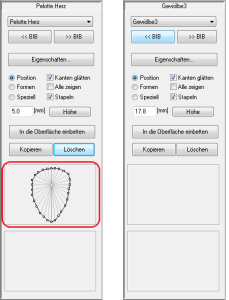
Point models: have a fundamentally different structure. As the name suggests, these models consist of individual points. The points themselves are connected by mathematical formulae so that the model can be displayed by the software. In GP InsoleCAD the connections between the points are shown as lines.
Point models can be adapted quickly and very individually by moving the points. A large part of the actual modelling is carried out by the software and the stored formulas. At the same time, this creates very round, naturally shaped models.
- If a model is inserted, the highest point of the model is always displayed as a coloured square.
- The currently selected model can be recognised by the pink coloured dot and the yellow-orange texture with the drawn lines. For point models, if the "Moulds" also shows the points by which the model is defined in addition to the highest point.
- You can recognise point models by the fact that the points are displayed in the toolbox for a selected model. This area is empty for surface models.
Transferring the measurement without a margin is particularly suitable if you want to copy an insert whose data you do not have in your library. In this case, you will need a black box to scan the old insert.
Select the measurement of the insert by pressing Ctrl + left click on the "Measurement" button. Then load any insert from the library from the standard workspace of the main window. You can now use the "3D" button and Ctrl + left click on "Take over" copy the insert.
If the insert meets your requirements, you can make the changes by clicking on this button "Take over". Using key combinations (see below) you can alternatively Measurement with edge or Measurement without edge take over.
| Key combination | Take over |
| left-click on Apply | the changes are adopted |
| Ctrl + left-click on Apply | the measurement without edge would be accepted |
| Ctrl + Shift + left-click on Apply | the measurement with edge is adopted |
The effective range specifies how far into the insert surface (in mm) is smoothed. The value applies to the entire edge from bale (inside) to bale (outside).
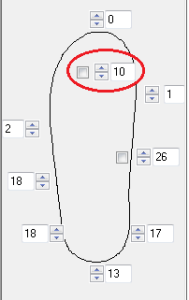
There are two ways to edit the edge of the insert. Either use the input fields with height values (in mm) to edit the edge or use the option to edit the edge with the mouse.
Editing the border with the height values
You can model the edge of the insole higher/lower by changing the height values in the input fields. Please note that you do not use the input field for the toe bridge (see Figure 22).
Note: When modelling the heel cup, it generally makes sense to edit the four rear values (marked in green). The easiest way to do this is to select the top left-hand value and enter the desired height using the keyboard. Use the Tab key to jump to the next field. Once you have changed the heights, press the Enter key and the new margin will be calculated.
You can also change the values using the arrow buttons, in which case changes to the border are calculated immediately
| Key combinationAmendment | |
| Figures | Enter the new edge height |
| Tab key | Next input field |
| Shift + Tab key | previous input field |
| Enter button | Adopting the changed edge heights |
Editing with the "Border editing" selection box
If you activate this option, you can use the standard views "I" and "A" to model the border with the mouse. To do this, click with Ctrl + left mouse button on one of the border points (coloured squares) and drag the border to the desired height.
Attention: To be able to use this option, you must be in the "Insert" (see 3.5.3.1 Insert / measurement).
If this option is selected, the toe bridge of the measurement is adopted with the specified height (in mm). If the option is not selected, the insole remains flat in the toe area.
When activated, the toe bridge is inserted in such a way that the free area behind the toes is filled. By reducing the height, the toe bridge is removed from above.
There are two views for processing a 3D measurement: "Insert" and "Measurement".
Before working with a 3D scan, you must first align the measurement with the zero line. To do this, select "Measurement" (see Figure 18), the 3D measurement is displayed. Switch to the view "I" or "A" to move the measurement with the arrow buttons (see below) so that it touches or slightly intersects the zero line (horizontal line) (see Figure 19). If the measurement is not on the zero line, the insert is pulled from the zero line to the measurement, which leads to the formation of a step in the insert.
Also check the position of the measurement in the "V" and "H". If the measurement does not correspond to the angle of attack, adjust the measurement accordingly using the arrow buttons.
| Key combination | Movement |
| Left/right arrow keys | Raise/lower the measurement left/right |
| Arrow keys up/down | Raise/lower the entire measurement |
| Ctrl + left/right arrow keys | Rotate the measurement to the left/right |
You can switch at any time between the "Insert" and "Measurement" view by selecting the corresponding option. In the view "Insert" to see the insert. Click on "Measurement", the 3D measurement is displayed.
By switching between the two views, you can get an idea of how well the insert fits the measurement data.
Via the button "3D" button will take you to the tools for the 3D design of insoles. To use these tools, you need the data from a 3D scanner (GP EasyScan, GP LaserScan, GP GipsScan). You can model the insole on the basis of a foot, foot foam, plaster or insole scan. If the button is deactivated, there may be two reasons for this. Either you have not selected a measurement or a measurement that does not contain any 3D information.
You can perform a 3D measurement with CTRL + left mouse button on the "Measurement" Select button.
Attention: It is also important for a 3D measurement that the foot axis and the bale line are set correctly in the measurement module.
Note: How to create a 3D measurement is described in the manuals for the respective measurement modules.
If you have selected a 3D measurement and an insert from the library, position it as described in 3.5.1.1 Position.
Once you have positioned the insert, you can click on the "3D" to model the 3D structure of the inlay.


