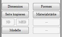
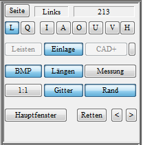
You can switch between different workspaces in the toolbox. If you change the workspace, the selection of tools available in the main window area changes. You can return to the standard workspace at any time by clicking on the "Main window" in the Function box click.
The top menus in the toolbox are used to manage the insert library. You can use the menus to influence how existing insoles are loaded from the library. You can load insoles in different shoe sizes from your libraries and save your own insoles in your library. The exact functions are described in section 3.4.1 Library management.
The toolbox is the area between the Function box and the Dimensions box. In this area, depending on the selected workspace ("Dimensions", "Moulds", "Material thickness", "Models"), various operating elements are displayed. By clicking on the "Main window" button in the function box can be used to switch back to the standard workspace at any time.
The GP Manager menu bar is located above the GP CAD module. Via the Arrow you can use the Exit GP CAD moduleYou will then return to the GP Manager start page.
The Question mark takes you to the GP Support Homepage (https://gpsupport.de). The computer requires an internet connection to load the page.
About the "Search/create customer" icon takes you to a view in which you can select a New CAD design or an already Existing CAD design can load/delete.
The GP CAD module itself is divided into the Work surfaceThe 3D model to be modelled is displayed here and a Toolbar on the right-hand side of the screen. The range of functions differs depending on which CAD modules you have purchased. You can see the activated modules in the function box (bars, insert, CAD+); if one of the buttons is not active, the module is deactivated. This should always be the case if you have not purchased the module or if you do not need these CAD functions at the workstation.
The following section describes the basic organisation of GP InsoleCAD shown. To GP InsoleCAD you have to search for the start of the GP Manager first a Select customers. How to select a customer is explained in the GP Manager manual in section 4.7 Searching for/creating a customer.
You can then access the GP CAD module via the GP Cad symbol (Figure 1).
GP InsoleCAD (CAD = Computer Aided Design) is used for the modelling of insoles and is part of the GP CAD module.
The GP CAD module consists of the GP InsoleCAD Module from the modules:
- GP OptiCADThe module enables the modelling and milling of mouldings.
- GP CAD+: Allows modelling of the underside of insoles.
The workplace where you GP InsoleCAD It is not important where your measurement data is collected or where your milling machine is located. The required measurement data can be transmitted via a network to the GP InsoleCAD computer.
You can incorporate information about your customer's foot into the design using various measurement methods (various 3D and 2D scanning methods).
After the design, the finished insoles can be transferred to the milling machine, another computer or an external partner. The finished modelled insoles are manufactured using a CNC machine.
Five points are decisive for optimally designed insoles:
- The measurement and its interpretation (3D scan, 2D scan)
- The inlay library and its customisation to your wishes/handwriting
- The software and its processing options and usability
- Your ability to apply and implement positions 1-3
- The milling machine and its accuracy or the accuracy of the milling step calculation
All elements have the same high priority.
Familiarising yourself with a CAD programme is unfamiliar for any beginner. Complex 3D objects are displayed on a two-dimensional screen and can only be modelled there.
This way of working differs considerably from traditional craftsmanship. Experience in handling the new tools of the trade can only be gained through practical work with GP InsoleCAD.


