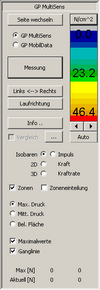
If the gait patterns of the two feet are displayed reversed, you can use the "Left Right" to switch the measurements to the correct side.

Note:
Before each measurement, you should ensure that the active zone (red rectangle) in the display area is set according to the object being measured (right or left foot) (see "Change page„).

By clicking on the button "Change page" button to change the active zone (red rectangle) of the display area. Another way to change the active zone is to click once with the left mouse button in the corresponding zone.

The force-time diagram is located below the display area. In it, the total force is plotted as a function of time. The total force of the left foot is shown as a red line and that of the right foot as a green line.

SQL_FussDruck MD_KraftZeit

Figure: Force-time diagram MobilData

SQL_FussDruck MS_KraftZeit

Figure: MultiSens force-time diagram

A simple left mouse click in the diagram selects a point in time and displays the respective pressure distribution image in the display area. The selected point is indicated by a black vertical marker. At the same time, the current force values are displayed in the "Current [N]" line in the force display area. The selected point in time appears in the top right-hand corner of the diagram.

If you move the marker while holding down the left mouse button, a "quasi real-time" display of the gait pattern is shown. The right or left arrow key on the keyboard offers another option for scrolling through the gait pattern. The scrolling direction corresponds to the arrows.

You can also zoom in on a specific area of the diagram. To do this, press the CTRL key and simultaneously drag a rectangle with the mouse (left mouse button) over the area to be zoomed. The entire measurement is displayed again by left-clicking while holding down the CTRL key.

On the display area of GP FootPrint the gait patterns are displayed after a measurement or after opening a measurement. However, the measurements of other measuring surfaces (e.g. hand, arm, etc.) can also be displayed.

Once the module is loaded, you will be taken to the user interface of the measured value recording module. The user interface is largely identical for the GP MobilData (insoles) and GP MultiSens (platform) hardware. This module is used to record measured values from the connected GeBioM hardware and process measurements.

Note:
The GP MultiSens and GP MobilData option switches (see red ellipse) are only visible if both hardware components have been purchased and activated in the module. The correct hardware must be set before the actual measurement!!!
SQL_FussDruck MS_Werkzeuge
SQL_FussDruck MD_Werkzeuge

Unlike MobilData, MultiSens always measures the two feet separately. For this reason, the sides can be swapped.

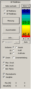
Differences in the GP MobilData and GP MultiSens toolbars (see above).

You can start the module from GP Manager via the menu "Trade fairs", select the menu item "GP FootPrint„.

Platform with the designation MS4 in the serial number

Description: Measuring platform with 2304 measuring points (FSR measuring foil)
Sampling frequency: max. 200 frames/s
Number of sensors: 2304
Resolution: 12 bit
Connection / interface: USB 2.0
Dimensions: 625 mm x 540 mm x 44 mm; 7 kg
Power supply: Power supply unit 12 V DC
Reproducibility: +/- 5 %

Platform with the designation MS2 or MS3 in the serial number

Description: Measuring platform with 2304 measuring points (FSR measuring foil)
Sampling frequency: max. 200 frames/s
Number of sensors: 2304
Resolution: 8 bit
Connection / interface: USB 1.1
Dimensions: 625 mm x 540 mm x 44 mm; 7 kg
Power supply: Power supply unit 12 V DC
Reproducibility: +/- 5 %

Before you connect the platform, you must have installed the "GP Manager" or "GP Manager_SQL" programme from the CD, as the drivers are on the CDROM in packed form.

The driver for a Multisens - MS4 (USB 2.0) can be found in the path:
C:\GeBioM_SQL\GPTOOLS \DRIVER\PSAA_USB2\DRIVER

The driver for a Multisens - MS2 or MS3 (USB 1.1) can then be found in the path:
C:\GeBioM_SQL\GPTOOLS \DRIVER\PSAA_USB1

(The italicised part of the path is the default directory during installation. If a different path was entered during installation, this must be entered above).

Attention:
The designation MS2, MS3 or MS4 is part of the serial number.

Driver installation:

  1. After installing the software, connect the platform to the power supply.
  2. Now connect the platform and the PC using the USB cable.
  3. After a short time, the operating system reports a newly recognised device and starts the hardware wizard. (Please wait for this dialogue box, up to 20 seconds may pass before it appears).
  4. In the dialogue box, please select the option "No, not this time" to activate it. Then "Further" click here.
  5. In the following dialogue box, please select the option "Software from a list..." to activate it. Then "Further" click here.
  6. In the next dialogue box, please only select the option "The following source as well..." button. Then click on the "Browse" button and set the path (see above). (i.e. for MS4: C:\GeBioM_SQL\GPTOOLS \TREIBER\PSAA_USB2\DRIVER)-You can also enter the path manually. Then "Further" click here.
  7. For the following Windows logo test please use "Continue installation" click here.
  8. Display of the end box.

Attention:
The installation may not yet be complete. If the hardware wizard appears again, carry out points 3 - 8 again.

Known installation error and help

The installation was carried out in the welcome window of the hardware wizard with the option "Install software automatically...".

Result: The installation has failed. The device is entered in the device manager under other devices (or in the USB area) and has an exclamation mark.
Help: Click on the USB device in the Device Manager and then click on the "Update driver..." in accordance with the installation instructions above.
  • Measuring platform
  • Power supply unit (12V)
  • Data cable (USB) 3 m (models 2304, 2048 and 4096 only)
  • CD ROM