MultiSens 2304 & MultiSens 2304BT
The platforms measure 550 mm x 455 mm and are 4 mm high. There is a measuring surface of approx. 390 mm x 390 mm on the top. This surface contains 2304 resistance sensors, i.e. approx. 2 sensors per cm². These sensors are scanned by an internal measuring interface with a total sampling rate of approx. 500 kHz, i.e. approx. 100 Hz per sensor. Data is transferred to the computer via the USB interface (model 2304) or Bluetooth (model 2304BT). The power supply is realised via an external 12V power supply unit. Model 2304BT can also be operated using rechargeable batteries.

SQL_MS_Foto


Remark:
Until the end of 2006, only the USB 1.1 standard applied. From 2007 the USB 2.0 standard applies !!!
Predecessor models:

MultiSens 2048 (no longer manufactured)
The platform measures 659 mm x 361 mm and is 24 mm high. There is a measuring surface of approx. 380 mm x 200 mm on the top. This surface contains 2048 resistance sensors, i.e. approx. 3 sensors per cm². These sensors are scanned by an external USB measuring interface with a total sampling rate of approx. 100 kHz, i.e. approx. 50 Hz per sensor. Data transmission is established via a data cable connected to the USB interface (USB 1.1 only) of the computer.
The power supply is realised via an external 12V power supply unit.

MultiSens 4096 (no longer manufactured)
The platform measures 665 mm x 575 mm and is 4 mm high. There is a measuring surface of approx. 515 mm x 515 mm on the top. This surface contains 4096 resistance sensors, i.e. approx. 2 sensors per cm². These sensors are scanned by an internal USB measuring interface with a total sampling rate of approx. 500 kHz, i.e. approx. 100 Hz per sensor. Data transmission is established via a data cable connected to the USB interface (USB 1.1 only) of the computer. The power supply is realised via an external 12V power supply unit.
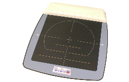
The MultiSens product range from GeBioM mbH comprises four measuring platforms that differ in terms of design and number of sensors.

Range: Nominal value: 100m with good battery, clear view and vertical orientation of the antennas
Transmission frequency: 433.19 MHz
Modulation: Amplitude scanning 2.4 kHz
Operating voltage: via 9-volt battery block (E-block, PP3) or via serial interface of a PC, if this can supply sufficient power (this option is not guaranteed)

The transmitter can control an external LED, which is attached to the edge of the camera lens for synchronised video recording. When the button on the transmitter is pressed, this LED shines into the lens of the video camera without being focussed and creates a recognisable red glow in the image. This marks the start/stop in the video image sequence.

Another option is to use the storage device if it can be brought into the picture during video recording. A very bright light-emitting diode can be attached to the back of the storage device, which lights up simultaneously when the button on the transmitter is pressed. To do this, the transmitter and storage device must be connected with the cable that is otherwise used to connect the PC and transmitter. Triggering by the PC is then not possible.

The transmitter can be controlled from a PC (start/stop by programme via the serial interface). If the COM interface is sufficiently powerful, the battery in the transmitter may not be required; however, this possibility is not to be expected with notebook computers.

The data logger must be fitted with an antenna that is plugged in to the left of the upper sole connection. The range and transmission quality are optimised if the antennas of the transmitter and datalogger are both oriented as vertically as possible.

This operating mode is used in conjunction with the "Measurement - expect trigger" command. Start or stop can then be triggered by radio by pressing the button on the transmitter. The button should be pressed for approx. ½ to 1 second. The indicator light lights up when a radio signal is sent. If it flashes, the battery should be replaced soon. The range may already be shorter if the light is flashing.

SQL_MDLoggerFunkteil Skizze

As with the standard version, the batteries are recharged with a small current when the data logger is placed on this device (stand-by charging).
This version also has a power supply unit that allows operation of the serial interface. A charging controller is also built in, which enables the battery to be charged quickly. However, the power supply unit and charge controller are only effective if the supplied cable is plugged between the storage device and the data logger. The meaning of the LEDs at the bottom right of the device is shown in the following diagram:

SQL_MDLoggerLadegerät Skizze

When the data logger is put down, the batteries are simply recharged with a small current that allows continuous charging (stand-by charging). A light-emitting diode lights up at the bottom right of the device to indicate charging.

Data can be output via the serial interface for test and diagnostic purposes. However, the serial interface is only switched on when the power supply unit is used. Data is only output if "Monitor" is set in the "Measurement" menu. The following output appears after the start (Texts in italics are explanations):

Message at programme start:

Data acquisition device for the measurement
of pressure distribution and additional analogue inputs
Version 3.00, 05/1999/GP-MD-2000 001
GeBioM
last number: serial number
Indication of the number of entries on the memory card and the free memory space.
xx entries in the directory Display of entries
xxxx KB free Display of free memory space
-> Monitor <- Setting: "Monitor"
Information about the sole matrix etc.
both soles Matrix 8 by 8
Total number of sensors 128
as an example (*) see below.
Information on parameters, characteristic and calibration data of the measuring soles
Identifier-left Identifier-left
Identifier-right Identifier-right
133 157 0 0 2638064 Password left,right,
Matrix type left, right,
Data logger calibration factor
data: Pressure sensors left 100 right 150 Relative gain e.g.100 %, 150%
554 454 380 314 265 217 179 146
0 1 0 0 0 2 0 0
0 0 0 0 0 0 0 0
0 0 0 0 0 0 0 0
0 0 0 0 0 0 0 0
0 0 0 0 0 0 1 0
0 0 0 0 0 0 0 0
0 0 0 0 0 0 0 0
Sole measurements left
823 674 568 469 396 323 268 219
0 1 0 0 0 2 0 0
0 0 0 0 0 0 0 0
0 0 0 0 0 0 0 0
0 0 0 0 0 0 0 0
0 0 0 1 0 0 0 0
0 0 0 0 0 0 0 0
0 0 0 0 0 0 0 0
Sole measurements right

(*) may appear here:
"both soles", "left sole only", "right sole only", "no sole",
"both insoles", "left only", "right only", "no insole"

"Matrix 8 by 8″, "Matrix 24 by 16",
"Matrix 8 x 8″, "Matrix 24 x 16"

In general, data output via the serial interface provides more information than is possible via the LCD.