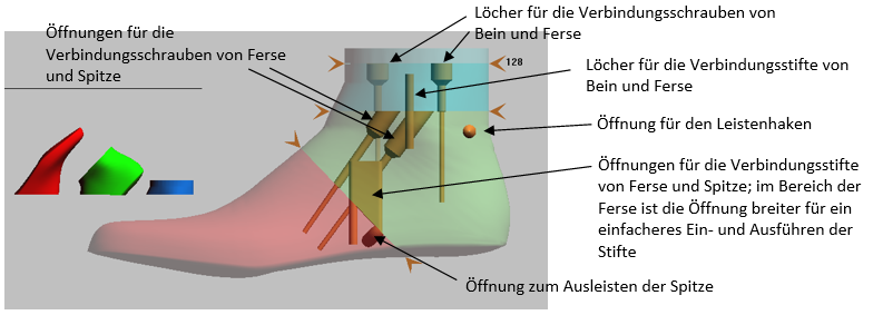
To assemble the split moulding, you will need the following connecting materials:

  • Metal pins: Ø 5 mm, l = 40 mm
  • Countersunk head screws: 4.5 x 70 and 4.5 x 50
  • M8 threaded rods, the length of which you can cut as required
  • Cable ties, for moulding the tip
  1. open the "GP LeistenDruck" module
  2. select the print job from the job list on

In the following, the processing of a leg last with the "Robust" set is explained; the processing can be transferred to the other sets and half shoe lasts:

  1. In the first step, adjust the cuts of the individual parts:
    • Pull the upper orange arrow on the leg to the desired height
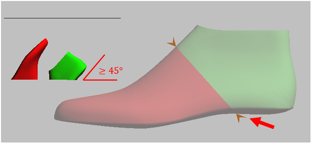
    • Drag the orange arrow on the plantar surface of the last to change the cut

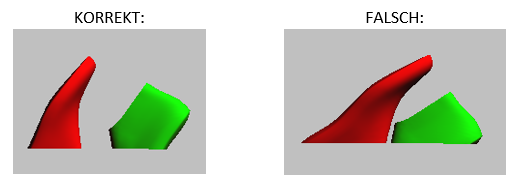
NOTE: Also make sure that the cut is not too shallow. The plantar surfaces should have an angle of at least 45° to the print bed, for example.

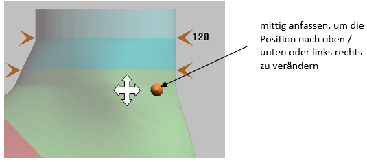
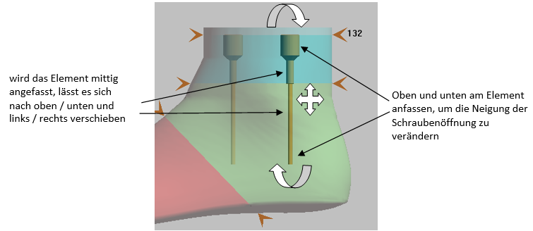
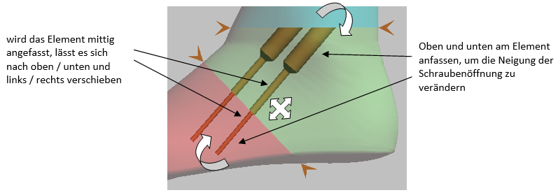
  • Changing the screws:

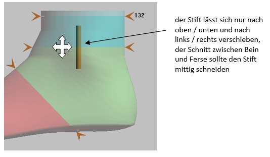
  • Changing the pins:

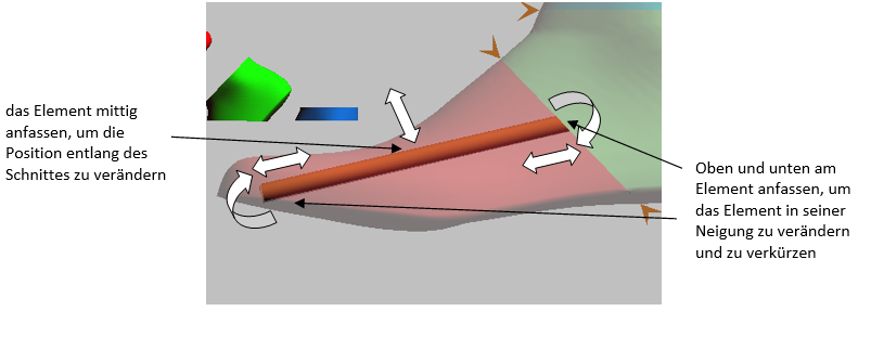
  • Changing the threaded rods:

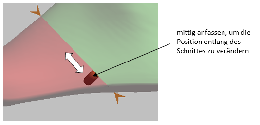
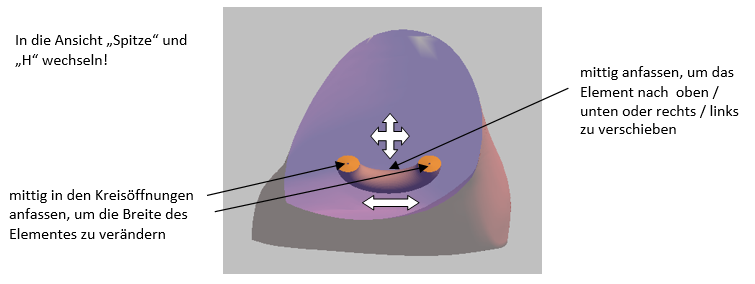
  • Changing the openings for moulding:

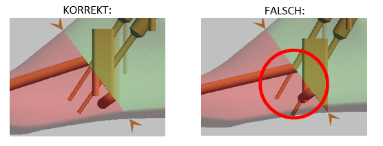
NOTE: Please also check the position of the individual elements in the other standard views and in the views of the individual parts

NOTE: Please ensure that individual openings do not overlap!

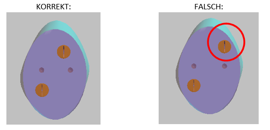
NOTE: The individual elements should be at least 3 mm from the edge of the moulding!

NOTE: The individual elements should lie within the moulding and not protrude from the moulding. The best way to check this is to turn the moulding.

 5. after you have positioned the elements, please click on "Create print file"

6. Switch to the right moulding and repeat the positioning of the elements and cuts

7. click on "Create print file"

8. once you have created the print file for both pages, click on "Done" and finalise the print job

  1. open the "GP LeistenDruck" module
  2. select the print job from the job list on
  3. a Low shoe lasts is displayed in two parts as standard:

Pull on the orange arrow on the plantar surface of the trial shoe (p. red arrow) to change the cut

NOTE: When positioning the cut, you should ensure that the individual parts are not positioned too flat on the print bed. For example, the plantar surfaces should have an angle of at least 45° to the print bed.

4. a Leg mouldings is divided into three parts as standard:

Pull on the orange arrows to change the cut. The upper orange arrow shows you the height of the leg last. Also make sure that the cuts are not too shallow when making the leg last.

NOTE: You can also print a leg last in two parts by also pulling the cut between the leg and heel up to the cut of the leg. However, always pay attention to the positioning on the print bed.

The "Create print file" button is used to create the print file for the page currently displayed. The progress and finally the storage location of the file are displayed below the button.

NOTE: Please note that you create the print file for the edited page directly before switching to the view of the other page.

Once you have created the print file for both pages, click on "Completed". The print job is then marked as "completed" and removed from the current job list.

If you tick the "Completed print jobs" box, you can reload the print job into the workspace for processing.

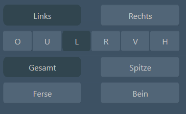
The following buttons can be used to switch between the individual views:

Use the "Left" and "Right" buttons to switch between the left and right bars.

NOTE: Please ensure that you first create the print file for one page before switching to the other page! Otherwise the settings and customisations will not be saved!

You can use the "O, U, L, R, V, H" buttons to view the moulding from different perspectives:

O - from above

U - from below

L - from the left (you can see the left slat from the outside and the right slat from the inside)

R - from the right (you can see the left moulding from the inside and the right moulding from the outside)

V - from the front

H - from behind

With the buttons "Total", "Toe", "Heel" and "Leg" you can either view the entire last / trial shoe or switch between the individual parts, such as toe, heel and leg.

When printing the moulding, you can choose between four sets with different connecting elements. The selected set is highlighted in blue.
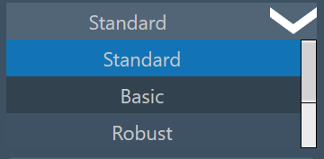
The set "Standard" divides leg slats into three parts as standard: toe, heel and leg. The toe and heel parts, as well as the heel and leg parts, are each connected to each other using two metal pins and two screws. Low shoe lasts are divided into two parts: Toe and heel.
With the set "Basic", leg lasts are also divided into just two parts: toe and heel. The two parts are also joined together using two screws and two pins. This set is recommended if you want to print leg mouldings with a low height.
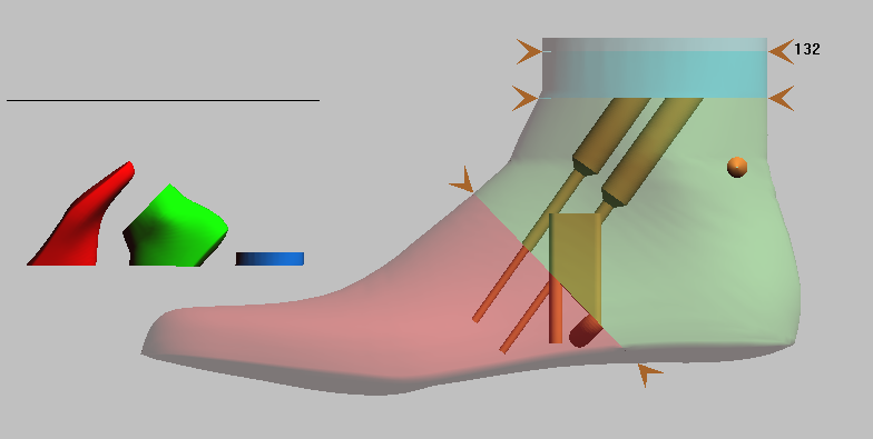
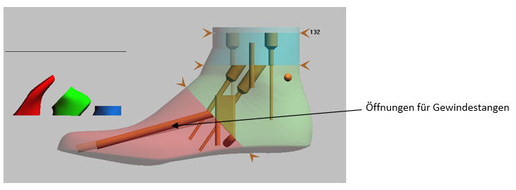
The set "Robust" should be used if your lasts are exposed to greater loads during shoe production, e.g. from a lasting machine. In this set, the leg lasts are divided into three parts as in the "Standard" set. However, in addition to the two pins and screws, two channels are built into the tip, in which you can install threaded rods to increase the stability of the last.
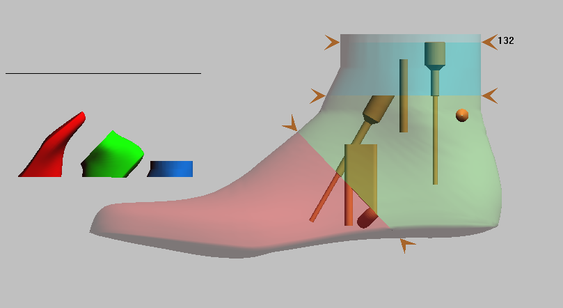
With the set "Kids", there is only one opening for one connecting screw and one connecting pin between the individual parts. This set is recommended for small, narrow mouldings.
If you want to change the stand selection of the set, go to the "GP Admin" module in the module overview:
Then open the "INI settings":

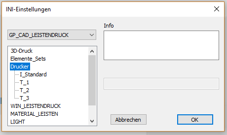
The following window opens:
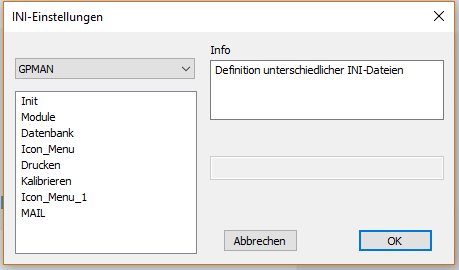
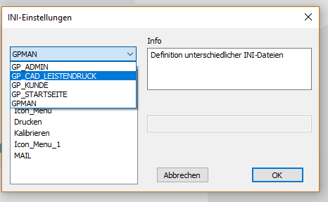
The correct INI must be selected in the drop-down menu: GP_CAD_LEISTENDRUCK
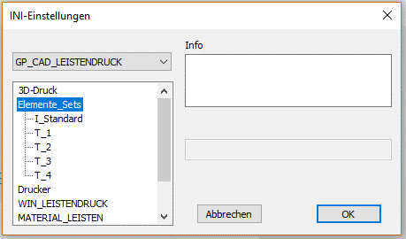
Then double-click to select the "Elements_Sets" parameter:
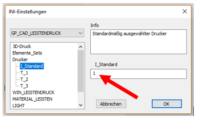
Now select the "I_Standard" parameter:
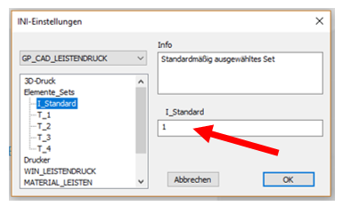
You can now enter the corresponding parameter in the field on the right-hand side (red arrow). The "1" stands for the "Standard" set, the "2" for "Basic", the "3" for "Robust" and the "4" for the "Kids" set. Click on "OK" to save the corresponding parameter. If you now open the "GP LeistenDruck" module again, the change should take effect immediately. Otherwise, please restart the GP Manager.

If you have selected a print job from the job list, you will be shown whether a trial shoe or a last is to be created. Accordingly, the button for the trial shoe or last is highlighted in dark grey.

If you have sent a print job for a trial shoe even though a last is to be produced, you can use these buttons to switch between the two print forms.

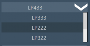
The 3D printer for which the print file is to be created is selected in the top list of the function bar. By default, your printer should be highlighted in blue in the list and therefore selected. If you have several different printers, you should ensure that the correct printer is activated when generating the print file.

You can assign your printer to our product designations in the following overview:

If the correct printer is not set by default, you can change this setting by going to the "GP Admin" module in the module overview:

Then open the "INI settings":

The following window opens:

The correct INI must be selected in the drop-down menu: GP_CAD_LEISTENDRUCK

Then double-click on the "Printer" parameter:

Now select the "I_Standard" parameter:

You can now enter the corresponding parameter in the field on the right-hand side (red arrow). The "1" stands for the LP 333, the "2" for the LP 222, the "3" for the LP 322 and the "4" for the LP 433. The corresponding parameter is saved by clicking on "OK". If you now reopen the "GP LeistenDruck" module, the change should take effect immediately. Otherwise, please restart the GP Manager.
The individual buttons and functions of the function bar are explained in more detail below, from top to bottom.