Please install the driver for the device before connecting the scanner to the PC via USB. Please always use the latest driver. You can find this in the download area on our support page: gpsupport.com
The power supply unit supplied is required to operate the scanner. Connect the power supply unit to the designated connection (2) on the front of the device.
The mains plug must remain accessible as it fulfils the mains disconnection function.
Do not place any objects on the mains cable. Also ensure that people do not step on the power cable or get caught in it.
 WARNING WARNING
Only use the original power supply unit for this device. The use of an unauthorised power supply unit can damage the device or be dangerous for this device.
|
Change view
 After selecting one of the six available views, the measurement is displayed in this view.
Bunion line and foot axis
After activating the view of below you can move the displayed bale line with the left mouse button. To adjust the foot axis, you can rotate the foot in the front or rear foot area by holding down the left mouse button.
Start measurements
![]()
Left-click on the [Start measurement] button to activate the scanner and start a new measurement.
Next, the separately installed driver for the scanner is started and automatically carries out the initialisation process.

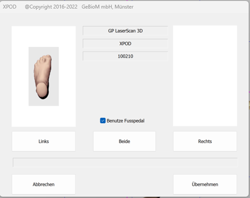
As soon as the scanner is initialised, all buttons are active. If you want to work with the foot switch, the "Use foot pedal" checkbox should be ticked. Then select the side you want to start with (left/right or both) and start the scanning process by pressing the foot switch or CTRL. If you have selected "Both", always start the scanning process with the left foot.
If you are not using a foot control, activate the scanning process by clicking on "Left" or "Right".
After scanning, a preview image is displayed. If both feet or just one foot have been scanned, the measurements are saved by clicking Apply. If a measurement is already open, you will be notified and you can decide whether to create a new file or overwrite the old measurement. The measurement is then displayed in the workspace.
Insert notes
![]()
You can create your notes by left-clicking in the free text field. These are saved with the customer under the measurement.
Move
To move the measurement, press the CTRL key and move the mouse in the desired direction.
Turning
To rotate the measurement, press the SHIFT key and move the mouse in the desired direction.
Rotate
To rotate along the longitudinal axis of the body, press the CTRL and SHIFT keys and move the mouse in the desired direction.
Zoom
Use the scroll wheel to zoom in and out of the measurement.
- Prevent light from falling directly onto the scanner plate. To enable scanning, it is important that the leg is not covered by clothing up to below the knee.
- The customer should be positioned as centrally as possible on the scanning surface
The customer must remain as still and upright as possible during the entire measurement process.
- Switch off the scanner using the switch on the back (1).
- Remove all cables from the back of the scanner and roll them up loosely for storage.
- Remove the footrests from the bolts.
- Fasten the transport lock:
- Remove the screw from the bearing slot (stow) (8)
- Lift the back of the scanner using the handle under the connections until the carriage in the scanner slides all the way forwards.
- Screw the screw into the locking slot (lock) (7) until the carriage is fixed in place
- Connect the power supply unit (2), the USB connection cable (3) and, if you want to use it, the foot pedal (4) to the back of the scanner.
- Connect the red USB connection cable to a normal USB port on your computer.
- red USB cable: at least quad-core CPU i7-6700HQ, 8GB RAM
- Plug in the power supply unit.
- Switch on the scanner using the switch on the back (1). If the button does not light up, check the connection of the power supply unit.
- The scanner can now be controlled with the GP FootMess 3D module.
- Place the foot scanner on a level, stable surface.
- Remove the transport locking screw (lock) (7) on the front of the scanner and screw it into the storage slot (stow) (8).
- Optionally, attach the foot supports on both sides of the scanner by sliding the recesses of the supports onto the bolts on the outside of the scanner.
- Establish a connection between the scanner and your computer as described below.