In GP foot measurement, an existing sole template (footprint) is displayed or switched to this view in order to scan in a sole template. When scanning, ensure the correct orientation of the template. The orientation of the footprint on the scanner must be selected so that the toes of the footprint are at the top of the screen after scanning.
Enter the values for the most important moulding circumference dimensions manually in the dimensions box. To do this, click in the desired field and enter the respective dimension in mm. Press the "Tab" key to move to the next field. The tab key must also be pressed again after the last digit. In the bottom field you have the option of entering relevant information about the measurement/customer.
Note:
The values should be those of the finished moulding (undersize/oversize already taken into account).
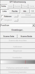
This box contains all the processing steps required to carry out a digitisation process (scanning) or to switch to certain views. The box is processed from top to bottom with the following steps:
- Setting the view via sole, inside, outside, heel or front (note: availability depends on the module).
- Setting the page via Left, Right
- Edit the scanner settings via "Settings ...". you can select a source to be used for measurement. If the scanner has already been set up, you can continue with step 4. Scanner settings: Colour resolution: Colour; DPI : 100
- Start the scanning process using the "Scan page" or "Scan both" button
- If necessary, define a partial area and then cut out using the "Limit" button
- Possibly setting a threshold value for detecting the foot outline using the white/grey slider.
- Remove all parts of the image that lie outside the outline using the "Delimit" button.
- Remove all background images required for the calculation using the "End processing. (Caution! It is no longer possible to edit the outline again)

Note:
If the result is not as desired, you can start processing again by clicking on "Calibrate". This only applies as long as the "End processing" button has not yet been used.
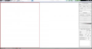
The digitised images of the foot are displayed in the workspace. Before digitising, the zone (red frame) of the workspace in which the images are to be displayed must be defined. Switching to the left or right zone is done by clicking on the corresponding area. The zones can also be activated or deactivated by clicking on the LEFT and RIGHT buttons.
Note:
If only one foot is scanned, make sure that the work surface corresponds to the foot to be scanned, i.e. right foot = right zone active or left foot = left zone active. The toes must always be pointing upwards in the zones. If they are pointing downwards, turn the template over in the scanner and repeat the scan.
The installation of the hardware depends on the type of scanner used. Please read the manual for the scanner you wish to install.
Any commercially available scanner can be used to scan footprints.
The measured value recording programmes cannot be installed independently. They are part of the GP Manager and are added during its installation.
The Measure menu takes you to the GP foot measurement recording programme. With
All foot measurement modules (TrittScan, FussScan, OptiScan, LaserScan 3D, KinectScan or DvScan) are managed in this module. Care has been taken to realise the administration in a standardised programme interface. The modules are used to address the corresponding foot measurement devices from GeBioM mbH and record measured values. These can then be further processed with GP CAD.
The following modules can be available:
- GP TrittScan
- GP FussScan
- GP LaserScan
- GP DvScan
- GP OptiScan
- GP KinectScan
Note: Only the modules that have been purchased and are therefore installed on your computer are activated.
With the GP foot measurement optical system, you can digitise your conventional footprints. You can use a standard flatbed scanner for this.
With the flatbed scanners from GeBioM GmbH, you can scan your patients' feet directly.
With the help of the GP foot measurement module, the orthopaedically significant foot dimensions in the insole are then determined and represented by an automatically calculated outline. You then define the points at which you have measured the most important circumference measurements and enter the values manually into the programme. All insole and circumference dimensions defined in this way are transferred to the GP CAD module for further design.

