- The distance between the Kinect and the foot was set too large/small.
- The foot must be held at as right an angle as possible to the Kinect. If this is not the case, the model in CAD will be "crooked".
- If the patient moves his foot strongly during the measurement, the measurement will be inaccurate.
Make sure that you have started the module by either clicking on GP FootDirect on the GP Manager start page or by selecting the correct measurement method in the GP FootMeasure module.
Position the Kinect so that it is not exposed to direct sunlight or light. In order to obtain accurate measurements, the area in front of the Kinect should be free of obstructions at a distance of 1.50 metres.
GP FussDirekt allows a patient's feet to be scanned directly.
- Hold the patient's leg so that it is as still as possible and there are no obstructing objects in the way. If you need to support the leg, place a support as close to the knee as possible.
- The space behind the foot should be as free as possible from other objects at a distance of 90-110 cm. Other objects could obstruct the measurements.
- As the foot is not loaded in this position, it is advisable to use a stable pane of glass. You can press this against the foot to simulate stepping on it. The glass pane does not interfere with the function of the Kinect.
- Hold the Kinect so that the plantar side of the foot is centred.
- Then click on "Scan page" and create a new measurement.
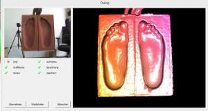
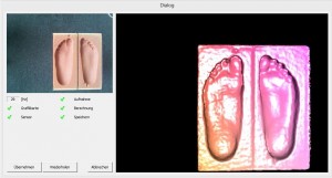
- The live image window of the 3D scanner opens. (see Figure 10)
- Make sure that the heel is pointing downwards in the picture.
- To achieve better results, you can move the Kinect slightly. The scan ends after 5 seconds.
- Once the scan is complete, set the line for the bale size and the foot axis. Then click on "Verticalise the foot axis„
- Distance between the camera and the plaster is too large/small
- There are other objects in the scanning area, make sure that the space behind the plaster is clear.
- The plaster is not positioned correctly on the turntable, note the angle that the plaster should have to the Kinect.
Make sure that you have started the module either by clicking on GP GipsScan on the GP Manager start page or by selecting the correct measurement method in the GP FootMess module.
Position the Kinect so that it is not exposed to direct sunlight or light. In order to obtain accurate measurements, the area in front of the Kinect should be free of obstructions at a distance of 1.50 metres.
- Place the turntable on an elevation of approx. 70 cm and fix the plaster on the turntable with the heel facing downwards. Ensure that the plaster cast is aligned at a 45 - 60° angle on the turntable. The camera should be slightly higher than the plaster cast (see Figure 9).
- The space behind the plaster should be free of other objects at a distance of 90-110 cm. Other objects could obstruct the measurements.
- Fix the camera on a tripod or wall mount so that the plantar side of the plaster is centred.
- Then click on "Scan page" and create a new measurement.
- The live image window of the 3D scanner opens. (see Figure 10)
- The measurement process can be actively started by clicking on the "Repeat" button. Start the measurement process when the plantar side of the plaster is facing the camera.
- After 1-2 rotations, you can end the measurement by pressing the "Ctrl" Press the button.
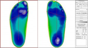
- A second window opens. Here you can use the red dots to position the foot vertically and horizontally (see Figure 11).
- You can define the cutting lines in the following window. Make sure that the upper red line is not higher than required for the later dafo. You can also specify the material thickness here. If you want to use the scan to construct a moulding, we recommend that you make an entry here. The material thickness is subtracted from the scan so that it is not displayed in the design in CAD.
1st method
- Distance between camera and step foam too small
- Interfering objects in the scan area
- Step foam does not lie straight
- Camera moves too fast
2nd method
- Distance between camera and step foam is not correct
- Step foam is not held vertically
- Fix the camera on a tripod. Then hold the foam in front of the camera at a distance of approx. 40-50 cm. Make sure that the foam is held vertically in front of the camera (90°) and that the camera is centred on the foam.
- If you only want to scan one step foam, make sure that you have selected the correct side. You can recognise this by the red frame (see figure 1, here the left side is selected). You can change the side by pressing :
- click with the mouse on the corresponding page.
- You can use the buttons "Links" or "Right" click here.
- To start the scan, select "Scan page"
- You can also scan two tread foams at the same time, in this case select "Scan both", it doesn't matter which side is chosen.
- Make sure that your arm disappears behind the step foam during the measurement and that only your hand appears in the measurement. This does not affect the measurement.
- The live image window of the 3D scanner opens. Important: make sure that the heels are pointing downwards.
- The measurement starts automatically after 5 seconds and ends automatically after a further 5 seconds.
- To improve the quality of the scan, you can move the foam slightly to capture the edge areas of the footfall foam. The measurement is then automatically accepted and is ready for further processing. An example of a good scan result can be seen in Figure 6.
- Once the scan is complete, position the line for the bale size and the foot axis. Then click on "Verticalise the foot axis„.
- You can enter the dimensions you have measured for the ball of the foot, heel and instep dimensions together with the measurement. This is particularly useful if you want to create a last in CAD with the measurement.
- If you want to scan your footboards the wrong way round (left foot on the right side, right foot on the left side), please contact us.
- The setup for the scan should look like Figure 4.
- Place the step foam on an elevation of approx. 30 cm. Make sure that the elevation does not protrude over the sides of the foam.
- The impact foam should stand freely on the table or on the floor within a radius of approx. 50 cm. Other objects could interfere with the measurements.
- If you only want to scan one step foam, make sure that you have selected the correct side. You can recognise this by the red frame (see figure 1, here the left side is selected). You can change the side by pressing :
- click with the mouse on the corresponding page.
- You can use the buttons "Links" or "Right" click here.
- To start the scan, select "Scan page„
- You can also scan two tread foams at the same time, in this case select "Scan both", in this case it does not matter which side is selected.
- The live image window of the 3D scanner opens. Important: here you must Make sure that the heel is pointing downwards.
- The measurement starts automatically after 5 seconds and also ends automatically after a further 5 seconds.
- To improve the quality of the scan, you can move the scanner slightly to capture the edge areas of the footfall foam.
- The measurement is then automatically accepted and is ready for further processing.
- Once the scan is complete, position the line for the bale size and the foot axis. Then click on "Verticalise the foot axis„.
- You can enter the dimensions you have measured for the ball of the foot, heel and instep dimensions together with the measurement. This is particularly useful if you want to create a last in CAD with the measurement.
- If you want to scan your footboards the wrong way round (left foot on the right side, right foot on the left side), please contact us.
Position the Kinect so that it is not exposed to direct sunlight or light. In order to obtain accurate measurements, the area in front of the Kinect should be free of obstructions at a distance of 1.50 metres.
There are two methods for scanning footfall foams, you can choose the method that gives you the best results.
To create a 3D scan, start the GP Manager. Select an existing customer or create a new customer. Then select "GP EasyScan" from.
This takes you to the module view of GP EasyScan. If you have not yet created a scan, the view will then look like Figure 1.
GP EasyScan is part of the GP FootMess module, which is why Figure 1 shows "KinectScan" is selected. If you want to create a 3D scan, make sure you do not change this setting.
You can select a different measurement or create a new measurement by clicking on the "User" icon in the menu bar.
A dialogue box then opens with all measurements that exist for the selected customer. You can also create a new measurement here (see Figure 3) and delete old measurements.
Double-click on an existing measurement to load it.
To install the hardware, you need the Kinect SDKand the Microsoft Visual Studio Redistributable Pack. You can download these two setup files here https://gpsupport.de/downloads/ download.
The files can be found under "GP Manager Installation\Vcredist„.
Please contact GeBioM Support after installation so that they can help you with the installation. GP EasyScan for optimum scanning results.


