1.Start - Module - GP foot measurement
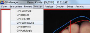
With the GP foot measurement optical system, you can digitise your conventional footprints. You can use a standard flatbed scanner for this.
With the flatbed scanners from GeBioM GmbH, you can scan your patients' feet directly.
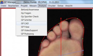
With the help of the GP foot measurement module, the orthopaedically significant foot dimensions in the insole are then determined and represented by an automatically calculated outline. You then define the points at which you have measured the most important circumference measurements and enter the values manually into the programme. All insole and circumference dimensions defined in this way are transferred to the GP CAD module for further design.
1.2.Installation - Software
The measured value recording programmes cannot be installed independently. They are part of the GP Manager and are added during its installation.
1.3.Installation - Hardware
The installation of the hardware depends on the type of scanner used. Please read the manual for the scanner you wish to install.
Any commercially available scanner can be used to scan footprints.
2.1.Work surface
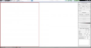
The digitised images of the foot are displayed in the workspace. Before digitising, the zone (red frame) of the workspace in which the images are to be displayed must be defined. Switching to the left or right zone is done by clicking on the corresponding area. The zones can also be activated or deactivated by clicking on the LEFT and RIGHT buttons.
Note:
If only one foot is scanned, make sure that the work surface corresponds to the foot to be scanned, i.e. right foot = right zone active or left foot = left zone active. The toes must always be pointing upwards in the zones. If they are pointing downwards, turn the template over in the scanner and repeat the scan.
2.2.Function box
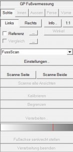
This box contains all the processing steps required to carry out a digitisation process (scanning) or to switch to certain views. The box is processed from top to bottom with the following steps:
- Setting the view via sole, inside, outside, heel or front (note: availability depends on the module).
- Setting the page via Left, Right
- Edit the scanner settings via "Settings ...". you can select a source to be used for measurement. If the scanner has already been set up, you can continue with step 4. Scanner settings: Colour resolution: Colour; DPI : 100
- Start the scanning process using the "Scan page" or "Scan both" button
- If necessary, define a partial area and then cut out using the "Limit" button
- Possibly setting a threshold value for detecting the foot outline using the white/grey slider.
- Remove all parts of the image that lie outside the outline using the "Delimit" button.
- Remove all background images required for the calculation using the "End processing. (Caution! It is no longer possible to edit the outline again)

Note:
If the result is not as desired, you can start processing again by clicking on "Calibrate". This only applies as long as the "End processing" button has not yet been used.
2.3.Dimension box
Enter the values for the most important moulding circumference dimensions manually in the dimensions box. To do this, click in the desired field and enter the respective dimension in mm. Press the "Tab" key to move to the next field. The tab key must also be pressed again after the last digit. In the bottom field you have the option of entering relevant information about the measurement/customer.
Note:
The values should be those of the finished moulding (undersize/oversize already taken into account).
3.Functions
3.1.Sole
In GP foot measurement, an existing sole template (footprint) is displayed or switched to this view in order to scan in a sole template. When scanning, ensure the correct orientation of the template. The orientation of the footprint on the scanner must be selected so that the toes of the footprint are at the top of the screen after scanning.
3.2.Inside/outside
This function is only available with the GP OptiScan module. You switch to the indoor or outdoor view (camera is activated, image to be measured is displayed).
3.3.Heel/front
This function is only available with the GP OptiScan module.
3.4.Left/Right
By clicking on Left, Right you determine the zone(s) in which the digitised image is displayed and later processed.
3.5.Info
In this info field, you have the option of entering relevant information about the measurement. This information then also appears in the thumbnail view of the "Preview window".
This information also appears in the preview window of the GP Manager and can be changed there by double-clicking (in the information).
3.6.Reference/comparison
Here you have the option of clicking on the ![]() to select/call up a reference or comparison measurement. These are then available for selection in a preview window.
to select/call up a reference or comparison measurement. These are then available for selection in a preview window.

Select a data record and then confirm with OK.
By ticking the Reference or Comparison box, you determine whether the selected measurement is then displayed in the active window.
When selected, the reference appears as a blue line in the measurement. A comparison of different measurements can also be selected via a selection window with preview.
3.7.Selection field
Use the selection field to select the module with which you want to carry out the measurement.
Note:
Only the modules that have been purchased and are therefore installed on your computer can be activated.
3.8.Settings
The parameter dialogue of the connected TWAIN-compatible scanner is displayed. This dialogue is structured differently from type to type. Common to all types are the functions for setting the colour and scan resolution, for preview and full image scanning. Depending on the type, additional filters etc. can be set with which you can influence the scan result.
The following parameters should be observed for our TrittScan measurement:
Colour resolution (colour): Colour
Scan resolution (dpi): 100
Attention!!! It is essential to know the features of your scanner. Read Please refer to the manuals of your scanner !!!
3.9.Scan page/Scan both
A scanning process is triggered. The footprint is digitised and then evaluated. Use the corresponding button to select whether you want to scan the pages individually (active page, red border) or both pages directly.
Note:
If the template has not been accepted after scanning, check the scanner settings. To do this, click on the Set scanner button.
3.10.Calibrate
By clicking on Calibrate the editing can be cancelled. Previous outlines, dimension lines and boundaries are cancelled. Editing can be restarted.
3.11.Limit
If the outline is not recognised, you can hold down the left mouse button and drag a rectangle from the top left to the bottom right around the area that was not recognised. Then click on Delimit. Everything outside the rectangle is now deleted and the outline calculation is restarted.
3.12.Processing
If the outline is not recognised, you can change the binary threshold value for outline recognition here. To do this, enter a new value after Binary.
The threshold value setting works faster using the white/grey slider. To do this, click on a position within the bar (to the right or left of the vertical red marker), the effect of the new setting is displayed directly on the screen.
3.13.Correction of the outline
The outline can be changed by moving the green dots. To do this, move the mouse pointer to one of the green dots, then press the CTRL key and the left mouse button simultaneously. Now move the mouse pointer. Once you have reached the correction point, release the buttons.
Important:
Please wait for the recalculation of the outline.
3.14.Correction of the longitudinal axis of the foot
Move the mouse pointer to the toe point of the longitudinal axis (top), then hold down the left mouse button and move the mouse to the right or left. Once you have reached the correction point, release the buttons.
Important:
Please wait for the image to be recalculated.
3.15.Foot perimeter lines
After the automatic calculation of the foot outline, further dimension lines (circumference lines) are displayed. Depending on the settings in the configuration file, the small toe, ball of the foot, toe-in, chip and waist lines and the foot axis are displayed. You can check the locations of the circumference lines and correct them if necessary by clicking on the crosses with the left mouse button pressed.
Then enter the values manually in the programme's measurement box.
Attention:
Setting the above lines is important as they form the basis for adapting to the perimeter dimensions of the moulding when it is transferred to GP OptiCAD. Please also read the chapters on dimensions and fixing in GP OptiCAD. It is also important to place the foot axis, as the moulding will be aligned with the foot axis of the footprint after transfer to GP OptiCAD.
3.16.Verticalise the foot axis
All unnecessary information outside the outline is cut off, the measurement is enlarged and aligned with the previously vertical foot axis. This ensures a clean display when superimposed on the inlay or moulding in GP CAD.
3.17.Finish processing
Removes all images that were required to calculate the foot outline.
Attention!!! Processing again (i.e. a reset by clicking on Calibrate) is no longer possible. possible!!!
3.18.Print
Various expressions can be selected under this menu. Click on "Standard" to print out a current view. Clicking on the "Footprint" button in the Printer menu generates a 1:1 printout on special footprint paper. The settings for such a paper format must of course also be set with the existing printer.
With the 1:1 printouts, the feet can be printed individually and with A3, both feet can be printed on one sheet.
If you select "Standard", you get the following view:
It is now also possible to save the current view as a PDF.
Note:
Entries that are stored in Info are also printed at the bottom of the paper.
5.Digitising a footprint


