
GP Import 3D manual

Operating manual
GP Manager
GP Import 3D
Version 7.5.2
1 Installation
GP Import 3D is part of the GP Manager and must be activated by a GeBioM employee. The module is installed in a support session, for which the computer requires an internet connection
2 System requirements and file requirements
2.1 System requirements
You can find out which system requirements you need and which operating systems are supported in our compatibility overview. You can find this and many other help topics on our support page https://gpsupport.de
We recommend a desktop PC. Windows 10 or even better 11 is absolutely necessary. Please note the graphics card - our recommendation:
http://www.go-tec.de/kompatibilitat-gp-easyscan-3d/
2.2 File requirements
The following requirements are placed on the files for import into the GP Manager.
In general, files of the following formats can be imported:
- STL 3D coordinates only
- OBJ 3D coordinates + texture
- WRL 3D coordinates + texture
The objects should have as few artefacts as possible.
If possible, the objects should be aligned beforehand. This speeds up the import process.
The software can be used to import completely 3D scanned feet, including the leg, footbeds and plantar soles. It is also suitable for importing the tops of insoles. To do this, the individual surface of the upper must be imported (not a closed solid or 2 surfaces).
The resolution should not exceed 20,000 triangular facets for footfall foams and insoles and 40,000 for plasters/feet. Please bear in mind that the resolution is for a foot and that a lower resolution also smoothes out unevenness. The higher the resolution, the longer the import will take.
Remark:
The GP Import 3D module cannot be used to import moulding data for OptiCAD.
3 Instructions for importing 3D files
3.1 Importing impact foams
The import programme is used to prepare a 3D measurement (STL / OBJ / WRL) automatically/manually so that it can be imported into the GP Manager.
Open the GP Import 3D module from the start page.
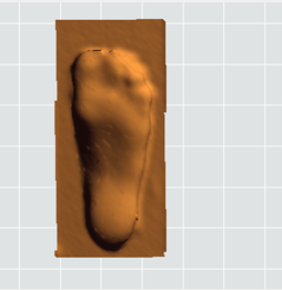
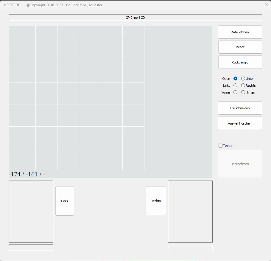
Click on „Measure“ and the following dialogue opens for importing the files:

Importing a measurement
The following formats can be imported:
- STL only 3D coordinates
- OBJ 3D coordinates + texture
- WRL 3D coordinates + texture
Click the [Open file] button at the top right to load the file. The Windows File Explorer opens to select a file. The desired format can be selected there.
The file is then loaded into the active window.
Manual alignment
Manual alignment can be used to adjust the alignment of the measurement. The measurement must be aligned for import in such a way that:
- the tip of the foot points upwards
- The vertical foot axis is
- The bottom of the foot is
- The sole of the foot is aligned as horizontally as possible to the floor
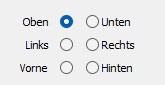
The three views with different editing options can be used for editing.

Turning
The measurement can be rotated around the depth axis in any view.
In the TOP view, CTRL can also be used to rotate around the other axes, similar to the CAD module. This allows the measurement to be brought very quickly into the correct alignment and then further aligned in the various views without CTRL.
Cutting
It may be necessary to remove unwanted parts of the measurement or artefacts.
This includes additional objects that may have been measured accidentally or the edges of the foam box.
The area of interest can also be cut out.
UP SHIFT + mouse -> drag the red selection area
SIDE/ DOWN SHIFT + mouse -> set the red line (remove leg / foam box)


Manual processing procedure
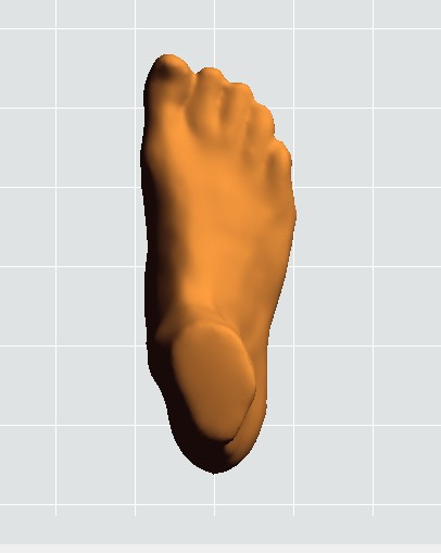
1. top view Align so that the toe / tip is at the top and the foot axis is vertical
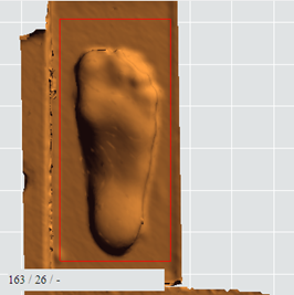
Select the area of interest with the red box and click on [Cut out].
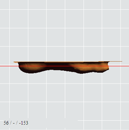
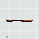
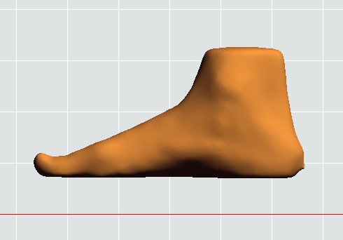
2. view SIDE sole of foot downwards / as horizontal as possible
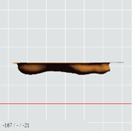
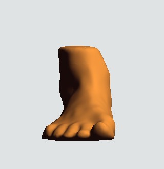
3. view BOTTOM sole of foot downwards / as horizontal as possible
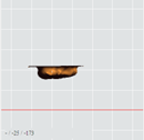
4. position the red line with CTRL in the PAGE/DOWN view and click on [Crop] or [Remove above the line]
5. removal of artefacts
Artefacts can only be deleted from the top view. Select the area with SHIFT + mouse -> drag the red selection area. Delete the selection by clicking on [Crop] or [Delete selection].

6. the last step is cancelled with [Undo]. Press [Reset] to reload the original file.
If you have also saved the appropriate MTL & JPG file (with the same name) in the OBJ folder, you can tick the [Texture] box so that the image files are transferred.

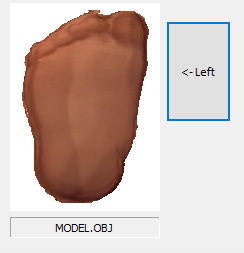
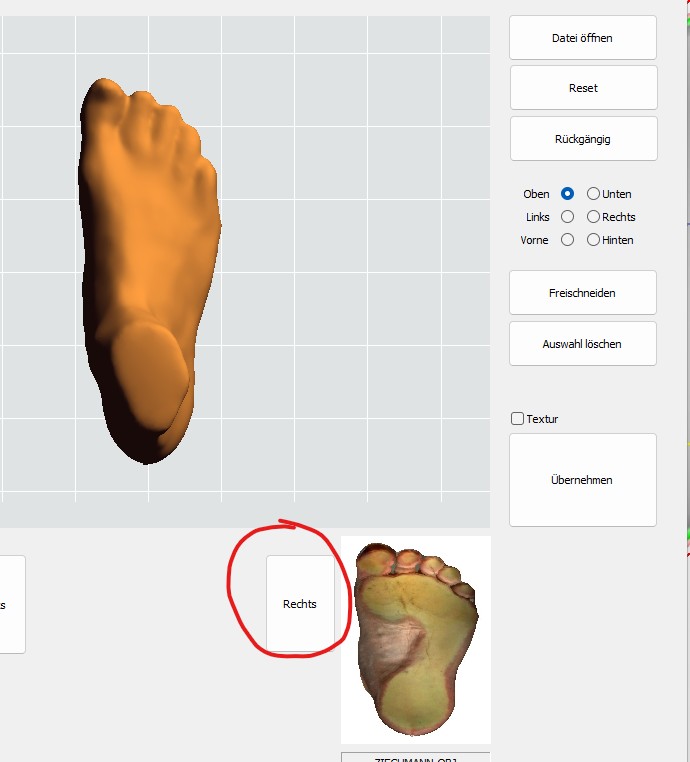
8. file of a page to sort left / right
Click on [Left] or [Right] to import the currently edited measurement for the desired foot side and display it in the corresponding window.
9. click [Open file] to load the right-hand measurement and follow the steps from 1 - 5.
The data can then be imported into the programme by clicking on [Apply]. They are then saved in the database and can be used in GP FootMeasure3D, GP FootMeasure and in the GP CAD module.
3.2 Importing whole and plantar feet
Click on Start measurement and the following dialogue opens for importing the files:
Importing a measurement
The following formats can be imported:
- STL only 3D coordinates
- OBJ 3D coordinates + texture
- WRL 3D coordinates + texture
Click [Open file] to load the file. The Windows File Explorer opens to select a file. The desired format can be selected there.
The file is then loaded into the active window.
Manual alignment
Manual alignment can be used to adjust the alignment of the measurement. The measurement must be aligned for import in such a way that:
- the tip of the foot points upwards
- The vertical foot axis is
- The bottom of the foot is
- The sole of the foot is aligned as horizontally as possible to the floor
The three views with different editing options can be used for editing.
Turning
The measurement can be rotated around the depth axis in any view.
In the TOP view, CTRL can also be used to rotate around the other axes, similar to the CAD module. This allows the measurement to be brought very quickly into the correct alignment and then further aligned in the various views without CTRL.
Cutting
It may be necessary to remove unwanted parts of the measurement or artefacts.
This includes additional objects that may have been measured accidentally or the edges of the foam box.
The area of interest can also be cut out.
UP SHIFT + mouse -> drag the red selection area
SIDE/ DOWN SHIFT + mouse -> set the red line (remove leg / foam box)
Manual processing procedure
1. top view Align so that the toe / tip is at the top and the foot axis is vertical
2. view SIDE sole of foot downwards / as horizontal as possible
3. view FRONT sole of foot downwards / as horizontal as possible
4. position the red line with CTRL in the SIDE/DOWN view and click on [Crop] if you want to cut something. You can also accept the file as it is if you do not want to cut any artefacts.
5. removal of artefacts
Artefacts can only be deleted from the top view. Select the area with SHIFT + mouseà dragging the red selection area. Delete the selection by clicking on [Delete selection].

6. the last step is cancelled with [Undo]. Press [Reset] to reload the original file.
7 If you have also saved the appropriate MTL & JPG file (with the same name) in the OBJ folder, you can tick the [Texture] box so that the image files are transferred.

8. file of a page to sort left / right
Click [Left] or [Right] to import the currently edited measurement for the desired footer and display it in the corresponding window.
9. click to load the right measurement and follow the steps from 1 - 5.
The measured values can then be imported into the programme by clicking on . They are then saved in the database and can be used in GP FussMess and the GP CAD module.