GP LaserScan 3D total foot one
1. safety instructions
Safety instructions
Laser safety instructions
Using the power supply unit
- Only use the original power supply unit for this device (12 V, 3.0 A). The use of an unauthorised power supply unit can damage the device or be dangerous for this device.
- Do not place any objects on the mains cable. Also ensure that people do not step on the power cable or get caught in it.
- Do not use the mains adapter if the device or the mains cable is damaged. Switch off the device and unplug the power adapter from the socket immediately.
- Never insert or remove the mains cable from the socket with wet hands.
- Disconnect the appliance from the socket before cleaning it. Do not use any liquid cleaners or sprays. Use a damp cloth for cleaning.
- Connect the mains adapter before connecting the mains cable to the mains socket.
- Unplug the mains cable from the socket before removing the mains adapter from the appliance.
3. scope of delivery
Please first check that the appliance is complete and undamaged. If in doubt, do not use the appliance and contact the manufacturer.
The scope of delivery of the GP Laser Scan 3D total foot one includes
- 1 GP LaserScan 3D total foot one (laser scanner for measuring the entire foot)
- 1 power supply unit (12 V, 3.0 A )
- 1 USB 2.0 connection cable (approx. 3.0 metres)
- 1 foot switch with connection cable (approx. 2.4 metres)
- 1 DVD or 1 USB stick (with drivers and tools)
- 1 USB dongle
- 1 instruction manual
- 2 side footrests
The packaging is reusable or can be returned to the raw material cycle. Please dispose of packaging material that is no longer required properly. If you notice any transport damage during unpacking, please contact the manufacturer immediately.

WARNING Make sure that the packaging film does not get into the hands of children. There is a risk of suffocation!
|
4th function
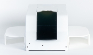
The GP LaserScan 3D total foot one is a 3D scanner that can now scan the entire foot in addition to the plantar information of the foot (i.e. from below). To do this, the device is placed on a firm, non-slip surface. With the laser technology of the GP LaserScan 3D tf one, the entire foot can be scanned in all three dimensions, whether fully, partially or unloaded. It only takes a few seconds to take the image and create a photo of the plantar view. Thanks to the laser technology, the feet are captured with millimetre precision and a detailed 3D image of the feet is obtained. The camera and laser unit are controlled and the measurement data is transferred to the PC via a USB port. The measurement data is displayed on the PC in the GP FussMess3D software module, where it can be further processed.
It must be possible to walk or run in front of and behind the device without tripping.
5. structure of the scanner
- Place the foot scanner on a level, stable surface.
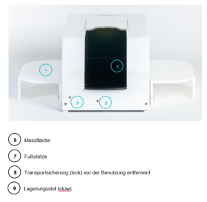
- Remove the transport locking screw (lock) (8) on the front of the scanner and screw it into the storage slot (stow) (9) (see Figure 2).
- Attach the foot supports (7) on both sides of the scanner by sliding the recesses of the supports onto the bolts on the outside of the scanner.
- Establish a connection between the scanner and your computer as described below.
6. connection to the computer
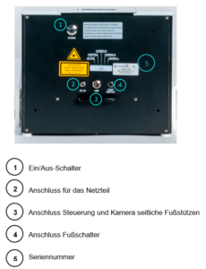
- Connect the power supply unit (2), the USB connection cable (3) and, if you want to use it, the foot pedal (4) to the back of the scanner (see Figure 1Error! Reference source could not be found.).
- Connect the USB connection cable to a normal USB port on your computer and plug the USB dongle into another port.
- Plug in the power supply unit.
- Switch on the scanner using the switch on the back (1). If the button does not light up blue, check the connection of the power supply unit.
- The scanner can now be controlled with the GP FootMess 3D module.
7. dismantling the scanner
- Switch off the scanner using the switch on the back (see Figure 1 (1)).
- Remove all cables from the back of the scanner and roll them up loosely for storage.
- Remove the USB dongle from the computer.
- Remove the footrests from the bolts.
- Fasten the transport lock:
- Remove the screw from the bearing slot (stow) (9) (see Figure 2)
- Lift the back of the scanner using the handle under the connections until the carriage in the scanner slides all the way forwards.
- Screw the screw into the locking slot (lock) (8) until the carriage is fixed (see Figure 2).
8. preparing a measurement
- Prevent light from falling directly onto the scanner plate. To enable scanning, it is important that the leg is not covered by clothing up to below the knee.
- Allow the customer to slide forwards in the scanner until their splint leg touches the cover flap.
The customer must remain as still and upright as possible during the entire measurement process.
9. quick guide to measuring with the LaserScan 3D total foot one
To start the module from the start page, you must first select a customer or create a new one. To do this, please click on the following symbol in the top right-hand corner ![]() . To create a new customer, click on
. To create a new customer, click on ![]() and fill in at least the mandatory fields (*). Via the arrow
and fill in at least the mandatory fields (*). Via the arrow ![]() or double-click on the customer name in the table to return to the start page and start the GP FussMess 3D module.
or double-click on the customer name in the table to return to the start page and start the GP FussMess 3D module.
To open the GP Foot Measurement 3D module, click on the button with the "GP Foot Measurement 3D" icon in the module overview of the GP Manager.
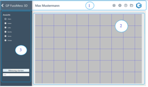
The user interface of the module consists of the menu bar (1), the workspace (2) and the toolbar (3).
After starting the module, the following menu bar is displayed:
The arrow (1) takes you back to the module overview. The name of the module (2) is displayed to the right. If a customer has been called up, the customer name (3) is displayed, otherwise this field is empty. Under the cogwheel button (4) you can make various settings regarding the colour display. If you have any questions or problems with the GP Manager, you can click on the question mark (5) to access the support page gpsupport.com. Click on the folder (6) to open the customer data and call up old measurements, for example. The GeBioM logo (7) is the home button that takes you back to the start page.
The toolbar is located on the left-hand side.
You can change the view of the measurement on the upper half.
You can start new measurements on the lower half and add notes in the free text field.
The exact handling of the individual functions is explained in the next chapter.
To move the measurement, press the CTRL key and move the mouse in the desired direction.
To rotate the measurement, press the SHIFT key and move the mouse in the desired direction.
To rotate along the longitudinal axis of the body, press the CTRL and SHIFT keys and move the mouse in the desired direction.
Use the scroll wheel to zoom in and out of the measurement.

After selecting one of the six available views, the measurement is displayed in this view.
Bunion line and foot axis
After activating the view of below you can move the displayed bale line with the left mouse button. To adjust the foot axis, you can rotate the foot in the front or rear foot area by holding down the left mouse button.
Start measurements
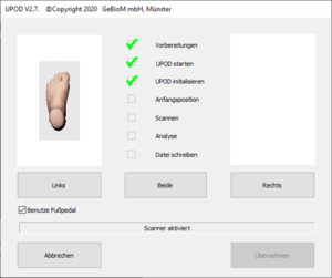
Left-click on the [Start measurement] button to activate the scanner and start a new measurement. If a measurement is already open, you will be notified and you can decide whether to create a new file or overwrite the old measurement.
Next, the separately installed driver for the scanner is started and automatically carries out the initialisation process.
As soon as the scanner is initialised, you can select whether you want to scan on the left, right or both sides. The measurement can then be started using the foot pedal (if selected) or by pressing CTRL. If both feet are to be scanned, you must start with the left side. After scanning, a preview image is displayed. If both feet or only one foot has been scanned, the measurements are saved by clicking on Accept. The measurement is then displayed in the workspace.
You can create your notes by left-clicking in the free text field. These are saved with the customer under the measurement.
10. use of the power supply unit
The power supply unit supplied is required to operate the scanner. Connect the power supply unit to the designated connection (2) on the front of the device.
The mains plug must remain accessible as it fulfils the mains disconnection function.
Do not place any objects on the mains cable. Also ensure that people do not step on the power cable or get caught in it.
 WARNING WARNING
Only use the original power supply unit for this device. The use of an unauthorised power supply unit can damage the device or be dangerous for this device. |
11. installation of the drivers
Please install the driver for the device before connecting the scanner to the PC via USB. Please always use the driver supplied on the CD/DVD or USB stick. It can be found in the folder "GPTools\Treiber\USOL_3D_FootScan_V1.2.6" or can be downloaded from our support page: gpsupport.com
12. cleaning and care
- Disconnect the appliance from the socket before cleaning it. Do not use any liquid cleaners or sprays. Use a damp cloth for cleaning.
- The measuring surface of the device must be cleaned with a soft cloth moistened with disinfectant before or after each use.
- Only use the appliance again when it is completely dry.
- Do not expose the device to direct sunlight and protect it from dirt and moisture.
13. metrological control
The device requires no maintenance or calibration. A metrological check is not required for commercial use.
14. user group
- The target group for this device is the specialist in the relevant field: orthopaedic (shoe) technician, engineer, biomechanist, ergonomist, etc.
- The system is therefore not intended for end users.
- In principle, the specialist should endeavour to expand and develop his or her specialist knowledge of the biomechanical relationships involved in walking, sitting and running, as the device only provides the basics and the specialist must decide personally on the measures to be taken.
15 Technical data
Name and model: GP LaserScan 3D total foot one
Data transfer: USB 2.0 / USB 3.0
Laser class: 2
Connection: 1 x USB, 1 x power
Dimension: approx. 520 mm x 270 mm x 220 mm
Weight: approx. 10 kg
Load capacity of the measuring surface: max. 130 kg static
Measuring error: +/- 1mm
Operating conditions: +5°C to +35°C, <80 % max. rel. humidity humidity
Power supply unit: 12 V, 3.0 A
In the course of continuous product improvements, we reserve the right to
We reserve the right to make technical and design changes.
16 Warranty and repair conditions
Please contact the manufacturer in the event of a warranty claim. If you need to send in the device, please state the defect and enclose a copy of the invoice.
The following warranty conditions apply:
- GeBioM mbH products are guaranteed for one year from the date of purchase. In the event of a warranty claim, the date of sale must be proven by the purchase receipt or invoice.
- Defects due to material or manufacturing faults will be rectified free of charge within the warranty period.
- Warranty service does not extend the warranty period, neither for the appliance nor for replaced components.
- Excluded from the guarantee are
- all damage caused by improper handling, e.g. failure to observe the instructions for use.
- Damage caused by repairs or tampering by the buyer or unauthorised third parties.
- Transport damage that has occurred on the way from the manufacturer to the consumer or during dispatch to the service centre.
- Accessories that are subject to normal wear and tear, such as batteries, sensors, etc.
- Liability for direct or indirect consequential damage caused by the device is excluded even if the damage to the device is recognised as a warranty case.


