Manual - GP VideoSupport V7
1.Overview and start of the GP VideoSupport software
The "GP VideoSupport" video analysis system is used to record and evaluate human movements. To do this, you use the software to analyse various segment positions and joint angle curves of the human body in motion.
Accordingly, you can record and evaluate natural movement sequences or the influence of corrective and/or stimulating measures (such as shoes, insoles, sensory elements, etc.) on the body.
You can work with up to four digital UEYE cameras, whereby different films and image sources can be synchronised. The connection to the PC is made via the USB interfaces.
The software offers the option of displaying up to four recorded video films simultaneously, allowing you to analyse and compare up to four different examination conditions.
Entering (segment) angles, setting perpendiculars and fading in grids makes it easier for you to analyse the images. Single images with zoom function and various playback speeds round off the evaluation options.
1.1.Starting the software
To open the "GP VideoSupport" software module, click on the "GP VideoSupport" button in the module overview.
Of course, all measurement recording programmes are part of the GP Manager. If you need help using the GP Manager (How do I create a customer? etc.), you will find this in the GP Manager user manual.
Note: Only the analysis programmes that you have purchased and therefore installed on your computer can be activated.
1.2.Overview of the software
After starting the "GP VideoSupport" software module, the following user interface opens: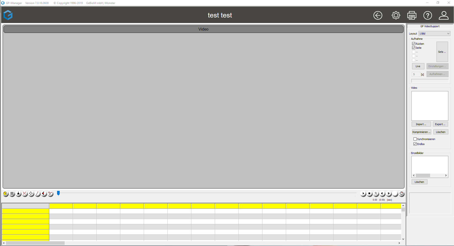
It is used to record and analyse the video sequences.
The user interface can be divided into three areas:
- The display area:
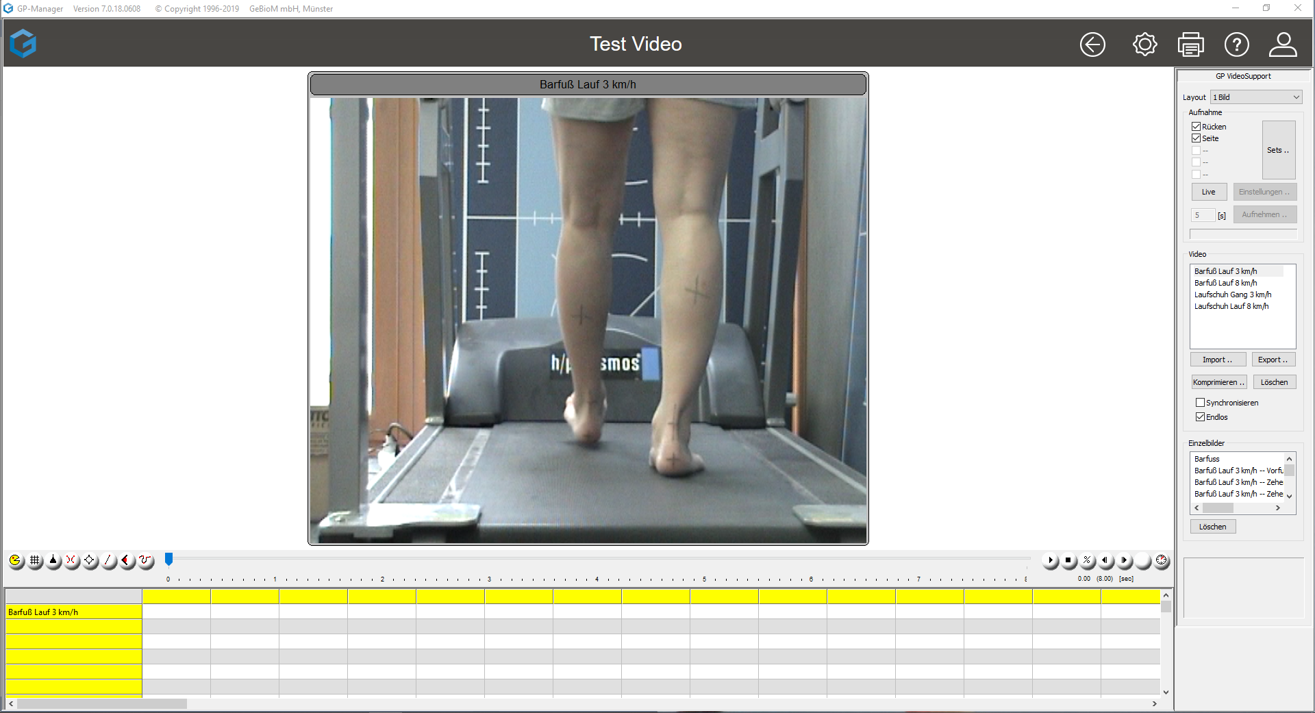
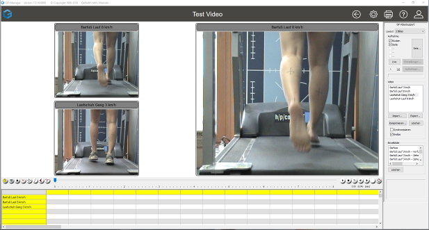
The video recordings and individual images can be displayed in the top left-hand section of the user interface. The display area can be divided into up to four images:


2. the evaluation range
In the lower part of the user interface, you will see a table showing the angle positions and parameters to be analysed (see Fig. 4).

Directly above the table is an icon bar that controls the evaluation of the video sequences (see Fig. 5). A more detailed description of the icons can be found in chapter 2.

3. the control bar
The operating elements of the software module are located on the right-hand side of the user interface.
These control elements are used to control the software. Here you can start, open, import and export video recordings, open and delete individual images and much more. Thanks to the clear arrangement of the operating elements, all functions can be started and called up directly. A detailed description of all the controls can be found in Chapter 2 - Controls.

2.Operation of the "GP VideoSupport" software
After a brief overview of the software, this chapter provides a detailed explanation of all the operating elements.
2.1.Listing of the operating elements
The control elements within the control bar allow the software to be controlled quickly and clearly.
Layout:
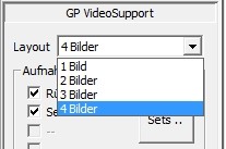
To specify how many images should be displayed, you can select the number of images on the top right-hand side.
Recording:
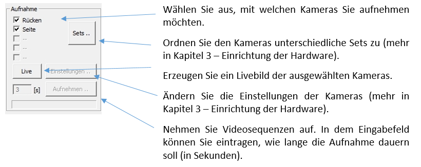
Video:
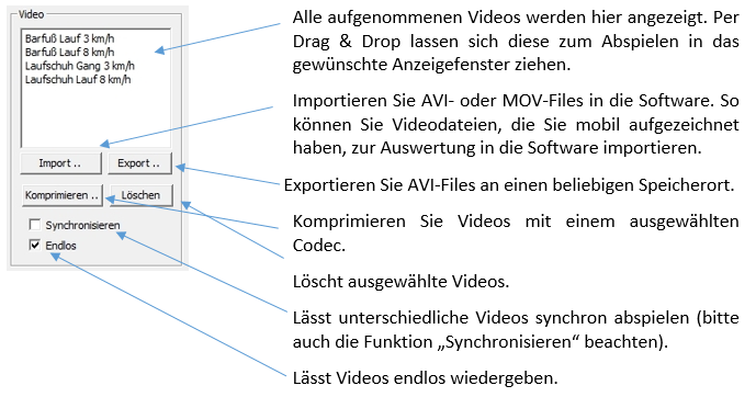
Single images:

2.2.Control elements of the evaluation area
The operating elements of the evaluation area support you in selecting individual images, entering angular positions and analysing conspicuous positions.
Delete:
![]()
This symbol deletes inserted angles / lines or similar. To delete an angle / line or similar, activate it in the single image and click on the symbol.
Scroll bar:

You can use the scroll bar to scroll forwards and backwards in video sequences and thus quickly reach the desired individual image.
Play, Stop, Slowmotion:
![]()
These buttons control the playback of the video sequences.
The "Play" button starts playback, "Stop" ends it, "Percent" slows down playback and the "Forward" and "Back" buttons help you to skip forward or backward through individual images.
NOTE: All of the following functions have the same basic operation. After selecting the desired function, the appearance of the mouse pointer changes.
Once you have selected the desired function, your normal mouse pointer turns into a hand: ![]()
You must now click on the video or single image in which the function is to be displayed.
Grid:
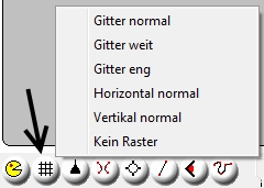 The "Grid" function enables auxiliary lines such as grids or vertical/horizontal lines to be projected over the single image or the video image.
Single image:
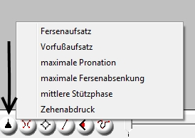 To create a single image from a video sequence, use the "Single image" function. In the video sequence to be edited, scroll to the section to be analysed and then select the correct name for the individual image.
Angle:
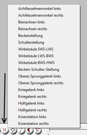
The "Angle" function is used to enter angles in a single image. To do this, click on the "Angle" button and select the desired designation of the angle.
Circle:
 The "Circle" function superimposes a circle on the video or single image. "Circle +4" and "Circle +12" makes the circle appear with additional auxiliary lines. This function is mainly used in wheel analysis to analyse crank positions.
Line:
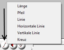
The "Lines" function displays additional auxiliary lines to help you analyse and clarify prominent points.
Free angles:
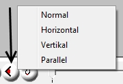 You can use the "free angles" function to enter additional angles that do not yet have a predefined designation.
Spline:
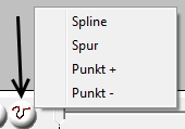 This function displays spline lines that consist of several points.
Synchronise:
![]() If you have two video sequences that were not recorded synchronously but still contain the same movement, the "Synchronise" function will help you to display videos synchronously. To do this, look for a distinctive point in time in the first video (e.g. heel strike or similar), then click on the "Synchronise" button and then on the selected video/image. Repeat this process for the second video.
If you have two video sequences that were not recorded synchronously but still contain the same movement, the "Synchronise" function will help you to display videos synchronously. To do this, look for a distinctive point in time in the first video (e.g. heel strike or similar), then click on the "Synchronise" button and then on the selected video/image. Repeat this process for the second video.
2.3.Other operation
Renaming of videos / individual images:
To rename a video or an individual image, simply double-click in the area above the displayed video / individual image.
Click in the upper grey area:

A dialogue window opens in which you can enter the new name.
Zoom:
To enlarge sections of a video or a single image, simply press the CTRL key on your keyboard.
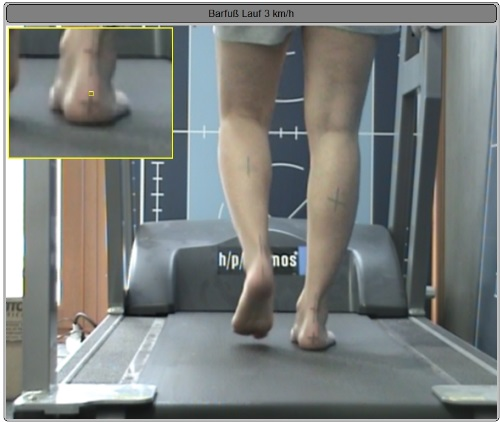
The area in which you are positioned with the mouse is then displayed enlarged.
Full screen mode:
To enlarge the display area to the entire monitor, simply double-click on the desired video / individual image.
Double-click again to exit full-screen mode.
3.Individualisation of the software
The "GP VideoSupport II" software gives you the option of customising almost all operating elements to suit your process. The "INI files", which are used to customise the software, help you to do this.
The "GP_VIDEO_SUPPORT.ini" file is important for you.
If you analyse several sports (e.g. running and cycling) with the same software, you can use different Ini settings at the same workstation and thus work with the correct default settings depending on the sport.
ATTENTION: Changing this file may result in the software no longer running correctly. Please contact our support team before making any changes.
Save the original setting before changing it.
3.1.Changing grid sizes, playback speeds, single image and video recordings
The "GP_VIDEO_SUPPORT.ini" file is located in the file path ./GPM_V7/GPSystem/GPSystem_xxx(depending on the name of the individual workstation)/INI.
It allows you to customise the displayed designations. It has the following structure:
[RASTER]
T_1 = Grid normal
T_2 = grid wide
T_3 = Grille narrow
T_4 = Horizontal normal
T_5 = Vertical normal
T_6 = No grid
P2_1 = 5/5
P2_2 = 3/3
P2_3 = 7/7
P2_4 = 0/5
P2_5 = 5/0
P2_6 = 0/0
The Grids section contains the division and designation of the grids to be displayed.
The designation is displayed after the term T_x = ... in each case.
If you want to rename this, replace the section after the "= sign" with the desired name.
The division of the grids is controlled via the "P2_x" section. The designation 5/5 means that the image contains 5 vertical and 5 horizontal lines.
[TEMPO]
T_1 = Super slow
T_2 = Very slow
T_3 = Slow
T_4 = Normal
I_1 = 10
I_2 = 25
I_3 = 50
I_4 = 100
The Tempo section determines the slow motion function. Use the term T_x = ... to determine the displayed name of the slow motion. I_x = ... specifies the speed (in per cent) at which the video is played.
[SINGLE_IMAGE_NAME]
T_1 = Heel attachment
T_2 = forefoot attachment
T_3 = maximum pronation
T_4 = maximum heel drop
T_5 = middle support phase
T_6 = toe print
The Single image_name section allows you to change the name of the individual images. You can change designations here, continue the list and/or add to it.
[VIDEO_Name]
T_1 = Barefoot 3 km/h
T_2 = Barefoot 8 km/h
The Video_Name section allows you to create a preselection of names for your video sequences. After recording video footage, a dialogue box opens in which you only need to select the name.
4.Hardware
4.1.Which cameras are supported
For the best possible utilisation of the "GP VideoSupport" software, we recommend U-Eye cameras from the manufacturer IDS. These are controlled via USB 3.0.
4.2.Hardware requirements for U-Eye cameras
The hardware requirements of the computer are extremely important so that up to four USB cameras can be controlled.
As computer features in particular are very fast-moving, the requirements listed here are to be understood as a minimum recommendation for the use of the "GP VideoSupport" software with the use of USB cameras (as of August 2015).
We generally recommend a desktop PC as a workstation for video analysis.
| CPU / Processor | Intel Core I7 - 3770K with 4x 3.5 GHZ |
| Working memory | 8192MB DDR |
| Hard discs | 1000 GB |
| Graphic | 1024 MB Geforce GTX 650 |
| USB | USB 3.0 |
| Network | 10/100/1000Mbit Lan, DSL capable |
Separate USB cards are required to connect several USB cameras to the computer. A diagram is provided to explain the difference between integrated and separate USB cards:

4.3.Installing the hardware
To connect the cameras to the computer, the drivers must be installed on the computer.
To use the U-Eye cameras, please install at least the U-Eye driver 4.6x.
A download of the driver can be initiated via our support page.
4.4.Setting the optimum image quality
When using Ueye cameras, many settings can be made using the "U-Eye Cockpit" camera software supplied. The contrast/white balance and the exposure time/frequency are important for the image quality. You can find out how to set these here.
4.4.1.Setting the contrast and white balance in the U-Eye Cockpit
- Start the "Ueye Cockpit" programme (desktop icon or under Start/Programs).
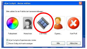
- Select the "Live video" button
- Select the desired camera by clicking on the green play button (in the top left menu) (if only one camera is available, simply click on the play button)
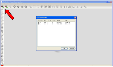
- The live image from the camera is now displayed. Next, the contrast of the image is set.
- The "Automatic contrast" button is used to set the contrast.
 After pressing the button, the contrast is automatically adjusted to the camera environment. The white balance is now carried out.
 - The "Automatic white balance" button is used to set the white balance.
 This button automatically sets the white balance with the camera environment.
 - Finally, the changes to the parameters are saved in the corresponding file. To do this, select the menu item: File -> Save parameters -> To file and select the following path: ./GPM_V7/GPSystem/INI.
The file for the first camera is
Config_Highspeed_UEYE_1.ini (Camera 1)
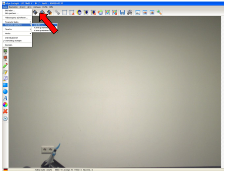
The changes in the GP Manager then take effect. The GP Manager must be restarted. If several cameras are used, the above points must be carried out individually for each camera.
4.4.2.Setting the exposure time, frame rate and pixel clock
- To set the exposure time, frame rate and pixel clock, start the Ueye Cockpit programme and select the desired camera (see section 4.d.i).
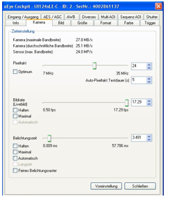
- The "Properties" icon is selected in the menu above.
 The "Camera" tab is selected. The "Pixel clock", "Frame rate" and "Exposure time" parameters are available there.
Set the pixel clock as high as possible without failure messages being displayed. The pixel clock depends on the camera used (heart rate). The higher the pixel clock, the higher the frame rate. In the "Frame rate" section, be sure to activate the "Hold" tick to retain this setting permanently.
The exposure time parameter influences the sharpness of the individual image. The optimum range is 4-7ms. This can be used to influence the brightness of the image and the sharpness of the individual image at the same time.
Please activate the "Hold" tick here too.
- Finally, the changes to the parameters are saved in the corresponding file. To do this, select the menu item: File -> Save parameters -> To file and select the following path: ./GPM_V7/GPSystem/INI.
The file for the first camera is
Config_Highspeed_UEYE_1.ini (Camera 1)
The changes in the GP Manager then take effect. The GP Manager must be restarted. If several cameras are used, the above points must be carried out individually for each camera.
