Manual - Mike 2 „Pro“ with upgrade 24/7

1.Operating manual

Manual
„CUBIX Pro“ with upgrade 24/7
3D printer inserts

GeBioM mbH
Wilhelm-Schickard-Straße 12
Germany - 48149 Münster
Phone +49 251 98724 - 0
Fax +49 251 98724 - 22
e-mail cubix@gebiom.de
www.gebiom.de
2.1. intended use
The 3D inlay printer Mike 2 with Upgrade 24/7 is a Fused Filament Fabrication (FFF) 3D printer. Its purpose is to print digital 3D models of insoles that are created in the software GP Manager InsoleCAD The process is designed to transform the moulds into physical objects (inserts) by depositing molten thermoplastic material (known as filament) layer by layer.
The printer has been specially designed to work with the filament Addigy® FPU 79AR8 of the company Covestro developed. Although the printer accepts other filaments (brand and/or material type), the use of these filaments does not provide optimal results and in some cases can lead to permanent damage to the machine.
Warning: Using filament that has not been authorised by the manufacturer/sales representative will invalidate the printer's warranty.
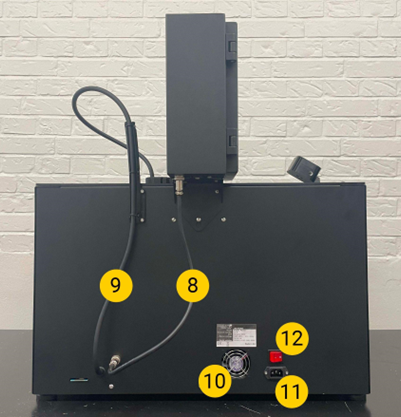
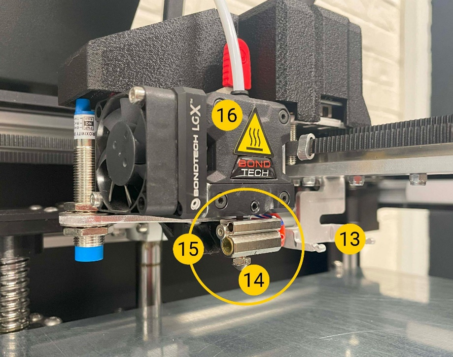
3.2. printer overview
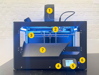
| 1-filament chamber For storing the filament used in the printer and to keep the moisture in the filament stable. 2 Print head For extrusion of the material. 3-Print bed Removable surface on which the object is printed. 4-USB connection For printing via a USB stick and updating the printer firmware. 5-LCD touchscreen To operate the printer. 6-On/Off switch Controls the printer's standby mode. 7-Ramp for removal 8-power cable for the filament chamber Cable that supplies the filament chamber with power. 9 Print head cable Power and data cable harness for the print head. 10-Exhaust fan To ventilate the electronics. 11 AC mains plug Input plug for the mains voltage. 12 Mains switch For controlling the flow of current to the internal power supply and the filament chamber. 13-Extraction fork 14-Nozzle 15-Hotend 16-extruder |
4.3. general safety information
This manual contains safety warnings and instructions that apply to the 3D printer, model "Mike 2" apply.
The following signs are used with the safety instructions.
 |
Information that is helpful for carrying out an action or avoiding security problems. |
 |
General warning sign: Warning of a potentially dangerous situation if the safety instructions are not followed (ISO 7010-W001) |
 |
Magnetic field warning (ISO 7010-W006) |
 |
Warning of electrical voltage (ISO 7010-W012) |
 |
Warning of hot surface (ISO 7010-W017) |
 |
Warning of hand injuries (ISO 7010-W024) |
The 3D printer Mike 2 may only be used after reading the safety instructions and the operating instructions.
Do not use the interior/chamber of the printer for any kind of storage.
Control the 3D printer Mike 2 always via the touchscreen on the front and/or the power switch on the back.
Do not use any material other than the compatible filament Addigy® FPU 79AR8 of the company Covestro into the print head.
Keep the front/door of the printer closed while the machine is in operating mode. Never reach into the machine during the printing process.
The main chamber of the machine (print chamber) has a backlight that indicates the machine status. The safe states for opening the front/door and entering the chamber are "Paused", "Idle" and "Print done", which are signalled by a steady or flashing green light.
All other light colours show "operating modes" in which the chamber must be closed. Further details on backlighting can be found in the operating manual in chapter 5.3.
Do not reach into the print area from the top of the printer. Only use the intended front side/door when removing the print object for cleaning and maintenance purposes.
Do not touch the nozzle/print head when reaching into the print area to remove the printed product. Nozzle parts become hot during printing.
Do not change any spare parts while the machine is in operating mode, unless expressly stated otherwise for maintenance or service reasons.
Always change the filament using the control panel (touchscreen) by following the standard procedure.
The 3D printer Mike 2 is not intended for use by persons with reduced physical and/or mental capabilities or lack of experience and knowledge, unless they are supervised or have received instructions on the use of the appliance from a person responsible for their safety.
Children should never use the machine unsupervised.
When moving the machine, always lift it from below. Do not lift the machine from the side. There is a high risk of damaging the functional structure of the printer. Information on unpacking the machine can be found in the instructions in the Quick Start Guide and in the operating manual in chapter 4 Preparing the printer.
5.3.1 Electrical safety
 |
The power supply unit should not be tampered with. If it needs to be replaced due to a malfunction, it must only be replaced with the same type of power supply by authorised personnel.
|
| |
An earthed main socket must be used. Ensure that the building installation has special means for overcurrent and short circuit.
|
 |
Always disconnect the appliance from the power supply before carrying out maintenance and service work, unless otherwise specified.
|
|
Only trained personnel should reach into the control chamber of the machine (accessible from the bottom cover of the machine), with the electrical and electronic parts.
|
|
Do not place any objects filled with liquids, such as vases or cups, on, around or in the machine. Take care not to pour any liquids into the system. They can cause a breakdown and/or fire hazard.
|
6.3.2 Mechanical safety
Keep away from the drive belts at all times. There is a risk of pinching during operation.
| The 3D printer Mike 2 contains moving parts. The force of the print bed is great enough to cause damage, so stay away from the print bed during operation.
Keep away from the drive belts at all times. There is a risk of crushing during operation.
|
|
 |
|
|
Always unplug the appliance before carrying out cleaning or service work, unless otherwise specified. |
7.3.3 Risk of burns
 |
There is a potential risk of burns as the nozzle/print head can reach temperatures in excess of 200°C. Do not touch the nozzle with bare hands.
Unless otherwise specified, always allow the machine to cool down for at least 20 minutes before carrying out maintenance work or modifications to the print head. |
8.3.4 Magnetic field
 |
Static magnetic field hazard. Due to the static magnetic field caused by the magnets in the printer, keep a distance of at least 4 cm between implanted electronic medical devices and implants that contain ferromagnetic materials. |
9.3.5 Emission hazard
Thermoplastics for 3D printing can lead to the release of ultra-fine particles (UFPs) and volatile organic compounds (VOCs), depending on the thermoplastic used and the settings of the 3D printer. Above certain concentrations (threshold values, TLV), these emissions can pose a risk. The concentrations are influenced by the filament and adhesive used, the printing conditions (e.g. printing temperature), the room volume, the air exchange rate (AER) and the number of printers in a room.
Depending on your specific situation, please observe other safety measures, such as a filter and/or a special ventilation system.
The use of printing materials / filaments from different suppliers may require additional safety measures. Always refer to the relevant information from the supplier of such filaments/materials and the safety data sheet of each specific material.
GeBioM mbH cannot be held responsible for any adverse effects of the use and/or performance of these materials.
10.3.6 Personal protective equipment
![]() The following elements are required for working safely with the 3D printer Mike 2 is recommended, especially for maintenance work:
The following elements are required for working safely with the 3D printer Mike 2 is recommended, especially for maintenance work:
- Tweezers: This is necessary to safely remove material residues from the nozzle.
- Thermal gloves: It is recommended to wear thermal gloves when cleaning the nozzle, as the nozzle may be hot during these procedures.
11.4. preparing the printer
12.4.1 Printer location
The printer is intended for use in an office environment with adequate ventilation and room temperature.
The printer requires a mains connection with an earth connection for power.
For an optimal working position of the operator, it is recommended to place the printer on a table, desk or other surface that is raised about 80 - 120 cm above floor level. Please note that the machine weighs 32kg.
For standard operations, access is only required from the front of the machine.
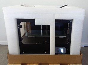
13.4.2 Opening the box
To access the printer, remove the top cardboard cover. This will expose the printer with its protective polystyrene.
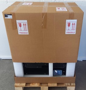
Remove the lid of the box upwards
Inside the box
14.4.3 What is in the box?
On top of the protective polystyrene you will find a small bag containing the printer parts.
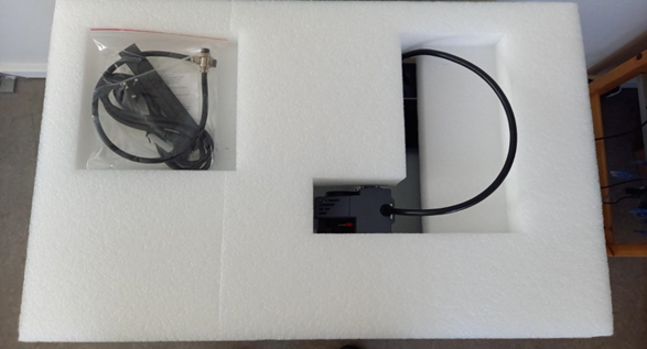
In the bag you will find:
- Filament tube
- Two small 1.5 mm thick plates
- Filament sensor for material escaping from filament box
- Cleaning filament
- 3mm hexagon spanner
- Power cable for the filament chamber
- Screws
- Cleaning brush for the nozzle
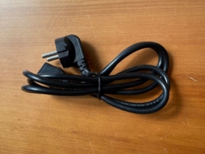
- AC power cable for the printer
- Power cable for the camera
- Mounting for the camera
- Camera

15.4.4 Lifting the printer
To lift the printer, hold it by the underside.
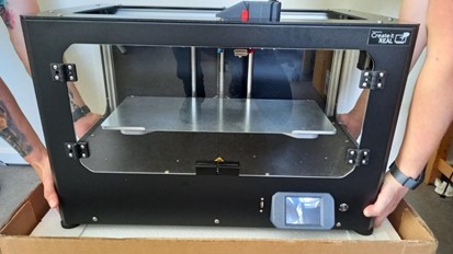
Lift the printer correctly
Warning: As the machine weighs 37.5kg, we strongly recommend using the machine exclusively with two persons to lift - one person from each side.
16.4.5 Removing the transport fastenings
1 | Remove the adhesive tape holding the print surface to the print bed. | 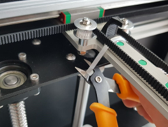 |
| 2 | Cut the cable tie that secures the ramp to the print bed for transport. | 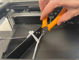 |
| 3 | Remove the ramp from the print bed. | 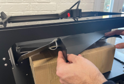 |
| 4 | Remove the black protective film from the surface of the print bed. | 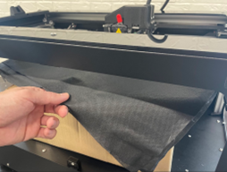 |
17.4.6 Switching on the printer
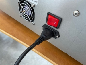
| 1 | Connect the supplied IEC AC cable to the plug on the back of the printer.
Connect the other end of the cable to the socket with earthing connection. IMPORTANT: The red switch must be in the 0 position (OFF) when the mains cable is installed. |
  |
|
2 |
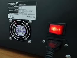
Switch on the mains switch on the rear panel.
This switch controls: 1. internal power supply 2. power supply to the filament chamber
|
 |
|
3 |
Use the ON/OFF button on the front to get the printer out of stand-by mode. Note: In stand-by mode, power is only supplied to the filament chamber and the internal power supply unit. All other parts of the printer are OFF. |
 |
18.4.7 Moving the print bed upwards
To remove the large box from the printer, the print bed must be lifted.
This is done via the menu Manual control:
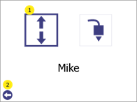
| 1 | Open the menu Manual control (1). |  |
|
2 |
Hold the button Z top (1) to move the print bed all the way up (when it reaches the limit, the print bed will stop moving).
Note: You can safely switch off the printer in this menu. |
 |
19.4.8 Switching off the printer
To avoid damage during the last part of the printer installation, the printer must be completely switched off.
| 1 | Switch off the printer. | 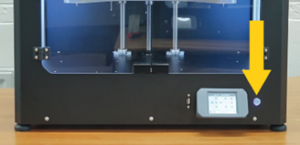 |
|
2 |
Switch off the mains power switch. | 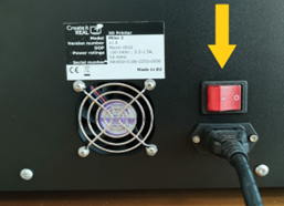 |
|
3 |
Disconnect the mains cable. |
|
20.4.9 Removing the large accessory box
| 1 | When the bed is raised, the large box can be removed from the printer. | 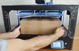 |
|
2 |
You will find the filament chamber (dryer) in the box. | 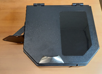 |
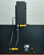
21.4.10 Mounting the filament chamber
To install the filament chamber on the printer, turn the printer so that you have access to the rear of the printer:
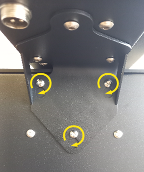
| 1 |
Remove the three screws from the filament chamber on the back of the printer and loosen them about 2 mm from the printer disc using the 3 mm Allen key supplied. |
 |
| 2 |
Slide the filament chamber onto the three screws and tighten them. |
 |
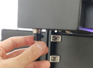
22.4.11 Connecting the filament chamber
Connect the 4-pin plug to the filament chamber and screw it tight. Connect the other end of the cable to the printer in the same way.
IMPORTANT: The filament chamber is always switched on when the main power switch is switched on. This ensures the correct environment for the filament in the chamber, even when the printer is in stand-by mode. Before switching off the filament chamber, please make sure that you have stored the filament in another location with controlled temperature and humidity.
 |
|
23.4.12 Function of the filament chamber
The filament chamber serves as a place to keep the filament used by the printer ready and at the same time to keep the condition of the filament stable.
When the filament chamber is supplied with power, a red light in the chamber switches on.
WARNINGIf the power supply is disconnected (power button on the back (OFF/0) or the cable has been removed), make sure that the filament is removed from the filament chamber and stored in a dry and warm (min. room temperature) environment.
24.4.13 Installing the printhead cable
| 1 | Locate the 2 fixing holes for the print head cable holder on the back of the printer. | 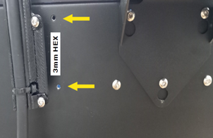 |
2 | Attach the bracket and tighten the screws using the 3 mm Allen key supplied. | 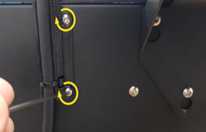 |
25.4.14 Installing the filament sensor on the filament box
| 1 | Open the chamber and locate the cable inside. |  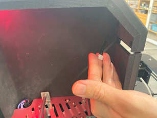 |
| 2 | Lay the cable out to the front and connect it to the sensor. | 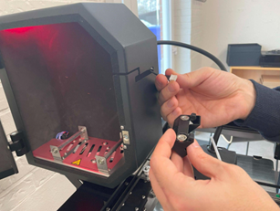 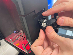 |
| 3 | Insert the sensor into the slot and pull it downwards. |  |
26.4.15 Installing the camera
A camera is used to automatically start a print, which checks whether the object has been correctly removed from the printer and ensures that the print bed is free for the next print. Carry out the following steps to install this camera.
| 1 | Remove the 2 screws located on the left side of the top printer frame. | 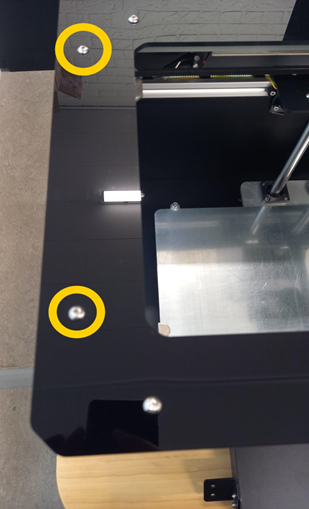 |
| 2 | Take the camera mount and the power supply unit. Place the power supply cable in the channel of the holder so that the power socket protrudes 6-7 cm. | 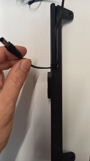 |
| 3 | Place the bracket on the left side of the upper printer frame, align the bracket with the holes of the removed screws and reinsert the fixing screws. When properly installed, the camera's power supply cable is concealed under the bracket. | 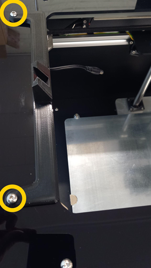 |
| 4 | Position the camera in the recess provided in the holder. |  |
| 5 | Connect the power cable to the camera. | 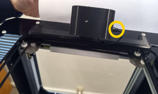 |
27.4.16 Installing the ramp
| 1 | Place the ramp on the prepared fixing holes. | 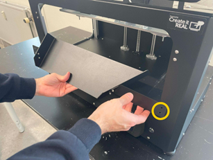 |
| 2 | Tighten the ramp with the four screws provided in the accessory bag. | 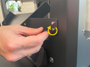 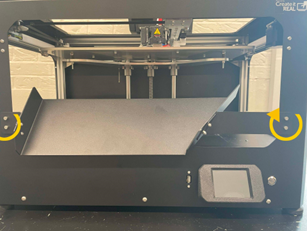 |
| 3 | Check that the ramp does not hinder the free movement of the print bed. To do this, use the button Z below in the option Manual control on the LCD screen. Using the screws that hold the main part of the ramp, you can adjust its position if necessary so that there is a gap of 3-4 mm between the edge of the ramp and the print bed. | 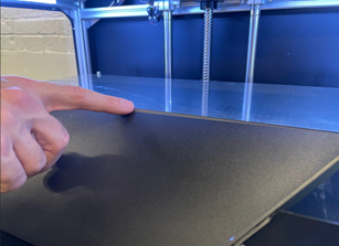 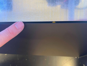 |
28.5. brief overview of the user interface
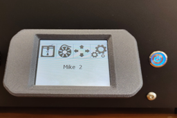
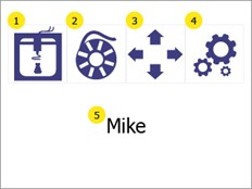
29.5.1 Main menu
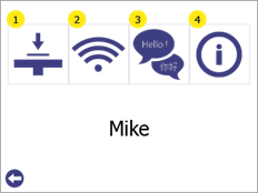
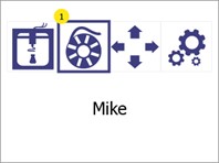
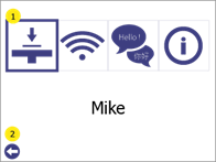
| 1. print USB
Enables printing via a USB stick. Further information can be found in section 11.1. 2. filament change Use the Filament change menu to insert and change the filament in the print head. Further information can be found in chapter 7. 3. manual control The manual control gives you access to the movement of the print head and print bed in all three axes of the printer. It also gives you access to manually extrude or pull the filament in or out of the print head. Further information can be found in chapter 12. 4. settings Enables access to an additional menu with the following functions: 1. print bed calibration 2. Wi-Fi configuration 3. language selection 4. printer information and firmware update Further information can be found in chapter Error! Reference source could not be found. 5. printer name Displays the name of the printer in the local Wi-Fi network. This is defined in the Wi-Fi configuration. By default, it is the name of the printer model.
|
 |
30.5.2 Settings menu
| 1. print bed calibration
Enables access to the print bed calibration process. For further information see chapter Error! Reference source could not be found.. 2. Wi-Fi configuration Enables access to information and configuration of the printer in the local network. Further information can be found in chapter 9. 3. language selection Allows the user to change the language of the printer menu. Further information can be found in chapter 6 4. printer information and firmware update Displays information about the printer and provides access to the printer's firmware update Further information can be found in chapter 13 |
 |
31.5.3 Printer lights
The printing chamber is equipped with lights that help the user to see inside, but also to indicate the status of the printer. Depending on the status, the colours change as follows:

32.6. language selection
|
1 |
Open the menu Settings (1) |  |
|
2 |
Select the Language selectionby pressing the language selection button (1)
Press the back button (2) to return to the main menu |
 |
|
3 |
The arrow (1) indicates the currently selected language; to select a new language, press the desired language to select it and then click on it again to confirm it as the new language.
Press the up (2) and down (4) arrow buttons to scroll through the list of available languages. Press the Back button (3) to return to the Settings to return. |
 |
33.7. change filament/insert filament
34.7.1 When should a filament change be carried out?
It is necessary to use the Filament change menu if:
- Filament is used for the first time
- an empty coil is to be replaced with a new coil
- a spool is to be inserted into a printer that does not contain filament
- filament is to be removed from the printer.
35.7.2 Preparation Insert filament
36.7.2.1 Inserting the filament spool
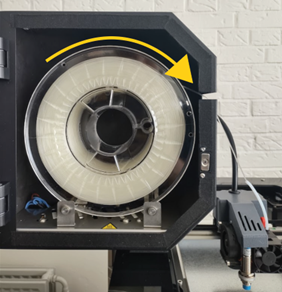
| When inserting a filament spool into the filament chamber, the spool must be aligned correctly to avoid problems.
The spool should be installed so that the filament is unrolled from the top, as shown in the illustration. |
 |
37.7.2.2 Feed filament through sensor
| 1 | Guide the filament forwards through the slot. | 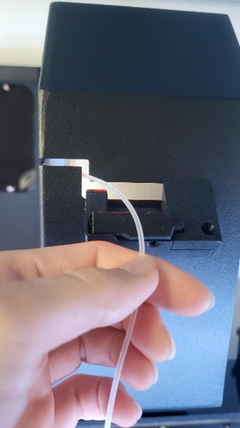 |
| 2 | Press down the clamp on the left-hand side so that the hole for threading the filament through is released. | 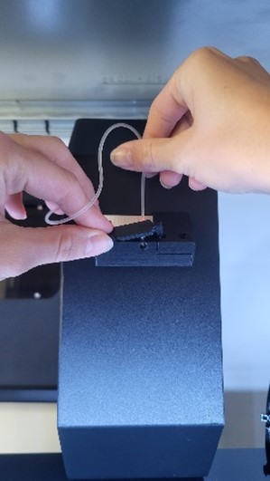 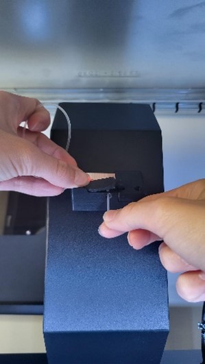 |
| 3 | Now thread the filament through the hole from the back to the front and then release the clamp. | 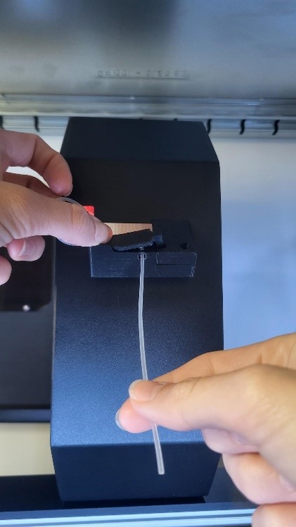 |
| 4 | Pull gently on the filament to check that it is correctly inserted and that the spool unwinds smoothly. Then cut off any excess material and insert the filament into the print head (see chapter 7.3). | 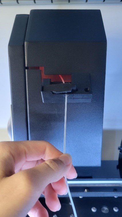 |
38.7.2.3 Checking the lever position
To ensure that the extruder is ready for printing, the lever should be in position 3. In this position, 3 notches are visible

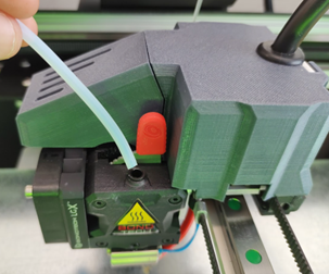
39.7.2.4 Attaching the filament tube
Insert the 10 cm hose into the print head inlet.
40.7.3 Insert filament/change filament process
The process for changing the filament always takes place in 2 stages - removing the old filament and inserting the new filament. If the filament is being inserted for the first time (there is no filament to remove), simply go through the process as if filament is already included.
| 1 |
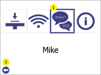
Open the menu Filament changeby pressing the filament change button (1)
|
 |
|
2 |
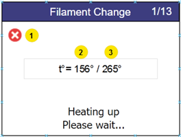
REMOVING THE OLD FILAMENTThe printer starts heating up automatically. The process continues as soon as the target temperature is reached.
During heating, both the current temperature (2) and the target temperature (3) are displayed. To cancel the process, press the cancel button (1). |
|
|
3 |
When the target temperature is reached, the printer starts a process to remove the filament. As soon as the filament can be removed, pull out the old filament and press the "Next" button (2). To cancel the process, press the cancel button (1). |

|
|
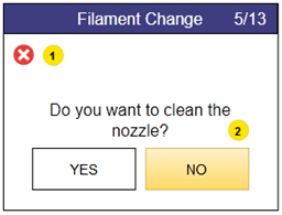
4 |
Cleaning the nozzle is optional. During the initial set-up, press NO (2) to proceed to the next step. To cancel the process, press the cancel button (1). IMPORTANT: It is strongly recommended to clean the nozzle after every 1 kg (1 spool) of material has been used. You can find instructions on how to do this under Cleaning the print head
|
 |
|
5 |
INTRODUCING THE NEW FILAMENTThe printer starts heating up automatically. The process continues as soon as the target temperature is reached.
During heating, both the current temperature (2) and the target temperature (3) are displayed. To cancel the process, press the cancel button (1). |
 |
|
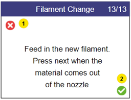
6 |
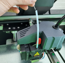
As soon as the printer has reached the target temperature, it automatically starts an extrusion attempt. Insert the filament into the filament tube and press it down until it is caught by the print head. Then release the filament and look under the print head. To cancel the process, press the cancel button (1).
|
|
|
7 |
As soon as the print head starts to extrude filament with a uniform shape and speed, press the confirmation button (2) on the LCD screen. The filament change is complete. To cancel the process, press the cancel button (1). |
 |
41.8. print bed calibration
42.8.1 What is print bed calibration?
It is an essential requirement of the 3D printing process that the print head is always at a constant distance from the print surface (print bed) when printing the bottom layer of the object.
If the gap is too large, the extruded material will not stick to the printing surface and will be pulled around by the head.
If the gap is too small (or the head and bed are touching), the material will not come out of the nozzle, which can lead to clogging. (The material will get stuck in the head and additional maintenance will be required to bring the printer back to an operational state).
The 3D printer Mike 2 has an algorithm for correcting inaccuracies in the alignment of the print bed. However, it is sometimes necessary to adjust the reference height parameter (starting point) with the help of the user.
43.8.2 To check whether the print bed is correctly aligned
A test pressure can be used to check whether the bed is correctly aligned. To do this, carry out the following steps:
| 1 | Open the menu Settings, by pressing the settings button (1). | 
|
|
2 |
Open the menu Print bed calibration (1) Press the Back button (2) to return to the main menu.
|
|
|
3 |
Open the menu Test print (1) Press the Back button (2) to return to the settings menu.
|
 |
|
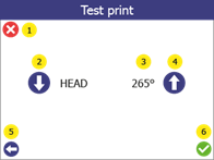
4 |
Select the print temperature of the print head for the test print. Change the target temperature (3) of the test pressure via the top (4) or bottom (2). If you use the standard filament Addigy® FPU 79AR8 is 265oC the correct value. Press the confirmation button (6) to start. Press the cancel button (1) to go to the main menu. Press the Back button (5) to return to the Print bed calibration to return.
|
 |
|
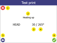
5 |
When the test print starts, the screen displays the status of the printer (2), the current temperature (3) and the target temperature (4). Press the cancel button (1) to stop printing and go to the main menu. Press the Back button (5) to stop printing and go back one step.
|
|
|
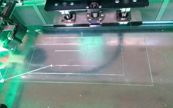
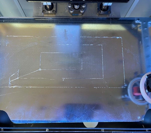
6 |
Test print Successful- 3 connected rectangles with evenly extruded lines.
- Extruded filament is clear and transparent. Test print failed - Uneven extrusion - Large parts without extrusion - Material stuck to the print head and not to the print bed. If the test print fails, carry out the print bed calibration (see below).
|
|

44.8.3 Print bed calibration
The menu Print bed calibration offers the possibility to optimise the print bed position of the printer in order to achieve better adhesion (bonding) of the extruded material to the print surface.
Attention: Before you start this procedure, make sure that the temperature of the print head below 80 oC and the Nozzle is clean (see section 14).
| 1 | Open the menu Settings, by pressing the settings button (1). |  |
|
2 |
Open the menu item Print bed calibration (1). Press the Back button (2) to return to the main menu. |
 |
| 3 | Open the menu Setting the print bed (1).
Warning! When you press (1), the print bed and the print head will move. Make sure that there are no objects or body parts in the print area. Press the Back button (2) to return to the Settings to return. |
 |
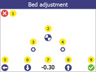
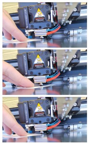
| 4 | 1. press the "Reference point" button (2). The print head moves to the reference point, takes a measurement and moves the print head and the print bed to its "zero" position.The offset value (7) for Mike 2 should be between -0.4 and - 1.2 -> These are slightly different for each printer. These values serve as a rough guide. For precise calibration, use a sheet of paper as described. If the measured value is outside this range, please contact support before proceeding. Note: (3) and (4) are calibration points that are used during maintenance (see chapter 2. take a piece of paper (normal printer paper, from a notepad, etc.) and carefully try to push the paper between the print head and the print bed without using too much force. 3. if it does not fit (distance is too small), use the down arrow (6) to move the print bed downwards until the paper fits in between. WARNING! Do not apply any force to the print bed by hand during this process. 4. the paper is now between the print head and the print surface. Move the paper slightly back and forth while moving the bed upwards one step at a time using the arrow (8) (each step is 0.05 mm). 5. press the down arrow once (6). 6. confirm the new removal by clicking OK (9). Press the cancel button (1) or the back button (5) to cancel the process (no changes are saved).
After this process, carry out a test print (see section 8.2) to confirm that the print bed calibration was successful. |
|
45.9. Wi-Fi setup
Before you can also access your printer via Wi-Fi, it must first be configured.
NOTE: The following application must be installed on the computer in order to use the 3D print inserts module: Microsoft .NET Core Runtime 3.1.16 (x86). If this programme is not installed on your computer, please contact support.
46.9.1 Generating a Wi-Fi configuration file
| 1 |
Open the GP Inlay Print module in the GP Manager.
|
|
|
2 |
Then click on the cogwheel in the top bar.
|
|
|
3 |
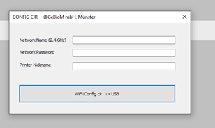
Fill in the fields: 1. the network to which you want to connect the printer (the printers only support 2.4 GHz networks). 2. the password for connecting to the network. 3. the printer name with which the printer is visible in the network. 4 Click on WiFi-Config.cir -> USB. A file with the name "wifi_config.cir" is now on the desktop. This is the configuration file required to configure the printer. |
 |
47.9.2 Connecting the printer to Wi-Fi
After the configuration file "wifi_config.cir" generated, place it in the root folder of an empty USB flash drive and carry out the following steps:
| 1 |
Switch on the printer |
|
|
2 |
Connect the USB stick to the printer. |
 |
|
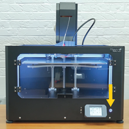
3 |
Open the menu Settings (1). |
|
| 4 |
Select Wi-Fi configuration (1) from Press the Back button (2) to return to the main menu.
|
|
|
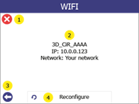
5 |
Select Reconfigure (4) Display of the configuration of the printer in the network in (2). Press the cancel button (1) or the back button (2) to return to the main menu. |
|
|
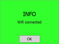
6 |
If successful, the confirmation message "Wi-Fi connected" will be displayed on the screen. At this point, the printer will be connected to the selected network and the printer name will be displayed on the printer's LCD screen.
|
 |


48.10. configuration of the camera
After installing the camera as described in section 4.15 Installing the camera, the following steps must be carried out to configure the camera.
The camera with the name Tapo_C100 is used for automatic extraction. After successful installation, the cameras have the name ID C100_######. The ###### = the last 6 digits of its MAC address, which is visible on the base of the camera and is displayed during the installation process.
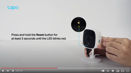
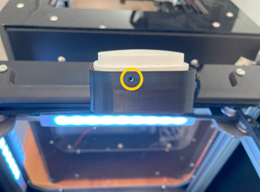
49.10.1 Resetting the camera
| Reset the camera to its default state by pressing the reset button on the camera. The process can take several minutes. It is complete when the LED flashes green and red (see video on the right). NOTE: The reset button is not accessible on the earlier version of the camera. The camera housing must be opened, which may require additional tools. | How to Reset Your Tapo Security Camera: Tapo C100/Tapo C110/ TC60 |
50.10.2 Installing the app and the camera
| 1 | Download the TP-Link of the Tapo app from the App Store or Google Play down. |  | ||
| 2 | Install the camera in your WIFI network To do this, you need a smartphone that is already connected to the WIFI network in which you want to add the camera. Follow the instructions in the app to connect. | |||
| 3 | Steps in the instructions: Press the dot: Add device. | 2. select the option Indoor cameras 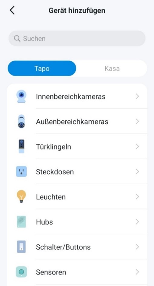 | ||
3. select the Tapo C100 device from the list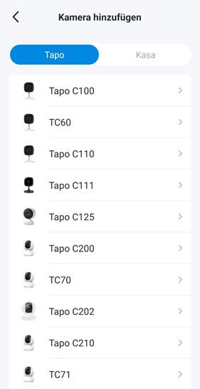 | Make sure that the camera flashes as shown in the instructions.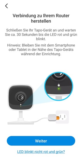 Make sure that the camera flashes as shown in the instructions. Make sure that the camera flashes as shown in the instructions. | |||
5. connect the mobile phone to the direct WIFI of the camera | 6. wait until the camera has been found | |||
7. select a WLAN network to which the camera is to be connected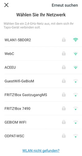 | Enter the password for the WLAN network and press Further 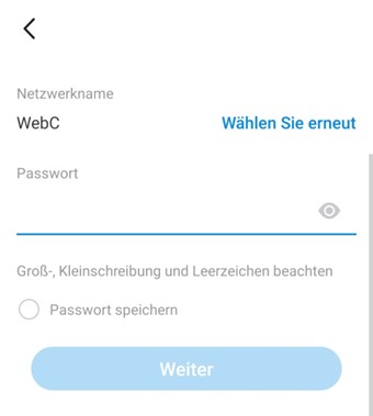 | |||
9. wait until the camera has established a connection with the specified network | 10. wait until the app and the camera are paired  | |||
11 It is recommended that you do not change the name of the camera ID and keep the suggested default name so that you can find the camera more easily later. Press the Further.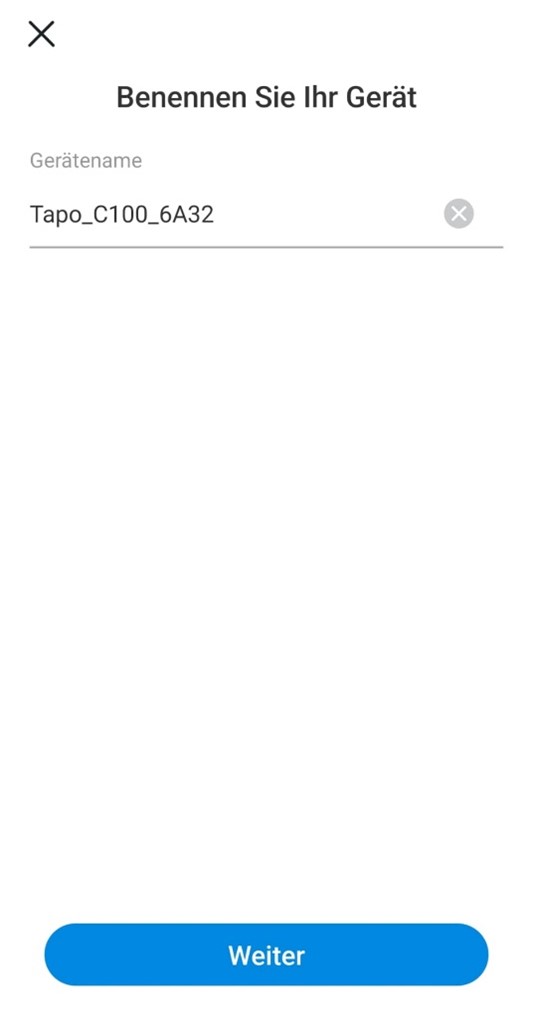 | 12. set the position and press Further This is only used by the Tapo app. 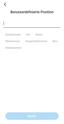 | |||
13. the camera is now paired and connected, press Class | Press Understood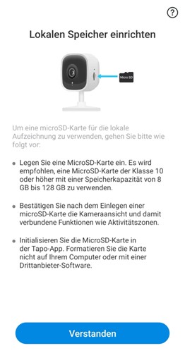 | |||
15. press Understood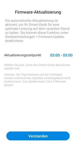 | ||||
51.10.3 Changing the resolution of the camera
It is necessary to change the resolution of the camera to ensure optimum operation. Follow the steps below.
1. open the camera in the app  | 2. open the camera settings menu  |
3. open the setting Video & Display 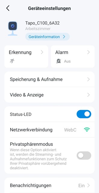  | |
4. select 1080P from 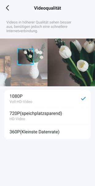 |
52.10.4 Removing the date and time from the display
It is recommended to remove the date and time from the display, as cameras with this setting have a higher success rate for extraction validation.
1. open the camera in the app  | 2. open the camera settings menu 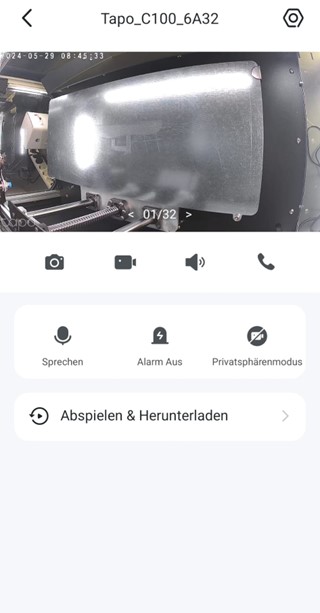 | ||||
3. open the menu Video & Display  | 4. open the menu Display Info screen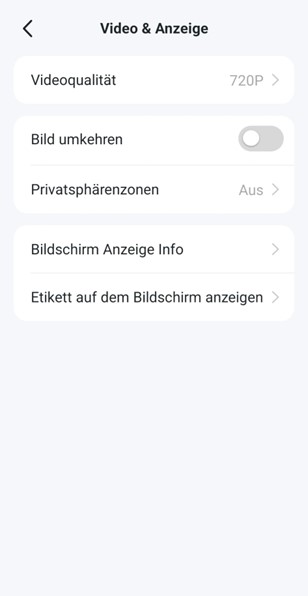 | ||||
5. Switch off all options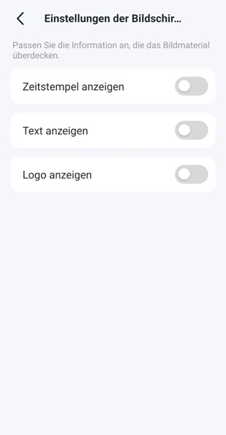 | |||||
53.10.5 Set up camera account (for connection with third-party software)
1. open the camera in the app  | 2. open the camera settings menu  | ||
3. open Advanced settings 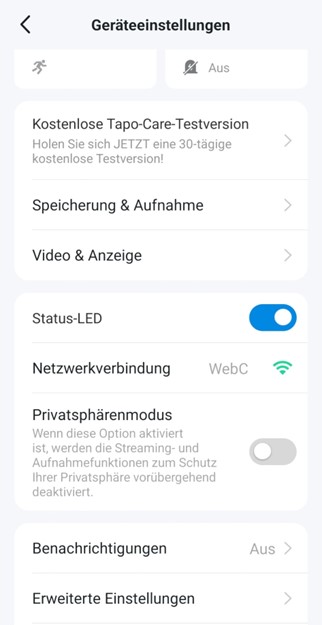 | 4. open the menu Camera account  | ||
5. select Create now 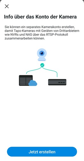 | 6. accept the general terms and conditions by clicking Understand and agree select 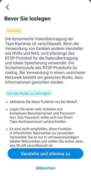 | ||
7. enter the user name and password and then click on Create These are currently as follows: !!! username: admin1234 Password: admin1234 (NOTE: This username and password are to be used as they are, they are not placeholders!) !!!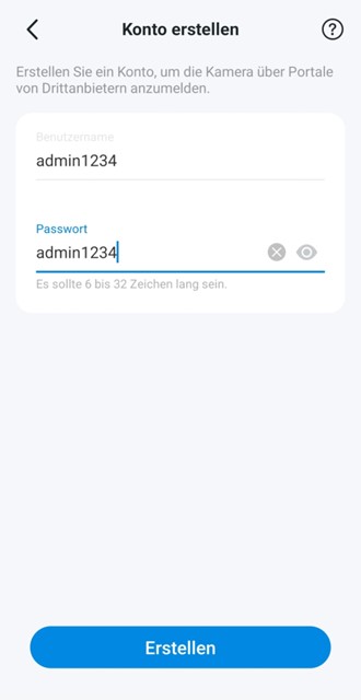 | |||
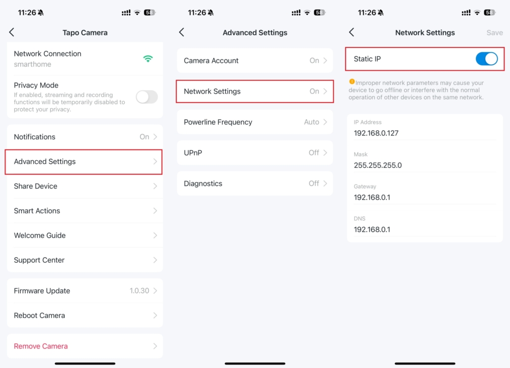
54.10.5.1 Setting up a static IP
Setting a static IP address for Tapo cameras ensures reliable and uninterrupted operation and at the same time ensures reliable and uninterrupted use of your cameras throughout the network. For continuous streaming via RTSP, connecting to an ONVIF compatible system or storing video on a NAS, setting a static IP address for your Tapo camera/doorbell is highly recommended.
Note: Not all models support the setting of a static IP address. This function is not available for:
- Certain older models, including C100/C200/TC60/TC70, hardware version 1.0 and 2.0.
- Battery-powered cameras
Support may vary depending on the model and firmware version.
Follow the instructions below to set up a static IP address for your camera.
- Open your Tapo app, select the camera and navigate to Device settings > Advanced settings > Network settings > Static IP
55.10.6 How to find the IP address of your camera
In some cases, the IP address of the camera is required to connect the camera to InsoleMaker.
1. open the camera in the app  | 2. open the camera settings menu  | ||
3. go to Device information | 4. there you will find the IP address 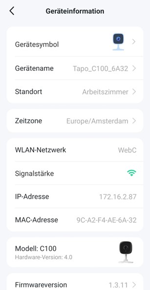 | ||
56.11 Before starting a printing process
Before you start printing, a few things need to be checked.
- The print area is located on the print bed.
- The Print bed is empty.
Make sure that there is nothing on the print area (e.g. another printed object). - The print bed is clean.
If the printing surface is dirty (dust, grease, etc.), the extruded material will not adhere to the surface. Check that the surface is clean. Further information can be found in section 14.1. - Enough filament
Open the filament chamber and make sure that there is enough filament on the spool. - Clean nozzle
Material may stick to the nozzle of the print head from previous use. If this is the case, remove it with tweezers or the cleaning tool. Further information can be found in section 14.2
57.12. starting a print
58.12.1 Printing via USB stick
| If the service allows it, the printer can print directly from a USB flash drive. | ||
| 1 | Open the menu Print USBby pressing the Print button (1). | 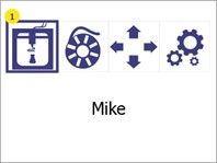 |
| 2 | A list of all available print files is displayed (1). The arrow indicates which file is currently selected. To select a file, press it (if not already selected) and then press it again to confirm the selection. Press the Back button (2) to return to the main menu. | 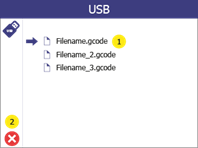 |
| 3 | On the print preview screen, it is possible to display the file name of the selected file (1). If a temperature other than the temperature set in the print file is required, it can be changed by pressing the temperature (3). To start printing, press the "Next" button (4). Press the Back button (2) to go back one step. | 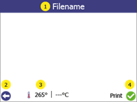 |
| 4 | The print preview screen shows the status of the print process during printing: (1) shows the status of the printer. (2) shows the current and target temperature. (3) shows the remaining time of the print job to be completed. (4) shows whether the printer is reading the print file from USB. If this is the case, do not remove the USB flash drive from the printer as this will cancel the print job. (5) shows the progress of the print in %. (7) shows the file name of the object to be printed. To pause printing, press the pause button (8). For more information, see section 11.3. To cancel the printing process, press the cancel button (6). | 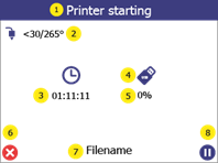 |
59.12.2 Printing via Wi-Fi
Printing via WLAN is started directly from the GP Inlay Print module in the GP Manager and the file is automatically transferred to the printer's internal memory.
| 1 |  | ||
| Open the GP Inlay Print module and select the relevant job from the job list. Select a page. Check whether a printer in the printer list on the left-hand side is idle (IDLE). Make sure that the printer is prepared for printing. See chapter 10. Start printing via the button Start printing via WiFi. The printer indicates that printing is being started via Wi-Fi. |  | ||
| 2 | The print preview screen shows the status of the print process during printing: (1) indicates whether the printer is heating or printing. (2) shows the current and target temperature. (3) shows the remaining time of the print job to be completed. (4) shows whether printing has been started via WiFi. (5) shows the progress of the print in %. (7) shows the file name of the object to be printed. To pause printing, press the pause button (8). For more information, see section 11.3. To cancel the printing process, press the cancel button (6). | 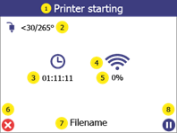 | |
60.12.3 Pause menu
The pause menu can be accessed at any time during printing.
| 1 | During printing, access the menu Break by pressing the pause button (1). | 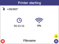 |
| 2 | From the pause menu it is possible to: Adjust the temperature (1).Perform a filament change (2) see chapter 7.Continue printing (3). To cancel the printing process, press the cancel button (4). | 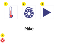 |
61.13. manual control
If required, it is possible to control the movement and heating of the printer manually.
1 | Open the menu Manual controlby pressing the manual control button (1). |  |
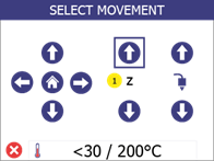
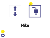
| 2 | Use the arrows (1) to move the print head in the working area. Press the home button in the centre (1) to move all axes to their "home" position (zero). Move the print bed up and down using the Z-axis arrows (2). Extrude or retract the filament with the print head control arrows (3). (Note that these buttons are deactivated if the print head temperature (5) is lower than the target temperature (6)) Start manual heating with the temperatures (5 and 6). When manual heating is started (the printer holds or reaches a certain temperature), the button a red border. If no manual heating is activated, the border is green. |  |
| 3 | Set the target temperature by pressing the down arrow (1) and the up arrow (4). To confirm the target temperature and start heating, press the confirmation button (7). The status of the heating controller is shown on the display (6), which shows IDLE when not heating and HEATING when heating. In addition, the lighting in the printer is white when the heating control is switched off and purple when the control is switched on. To stop heating, either go back to the main menu or reduce the target temperature (3) below 30 oC ("-" is displayed) and click on Confirm (7) Press the Back button (5) to return to the menu Manual control to return to the main menu. Press the Back button (5) again to return to the main menu. | 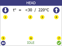 |
62.14 Printer information and firmware update
63.14.1 Info menu overview
| System information about the printer can be found in the information menu. This is usually used for customer support. | ||
| 1 | Open the menu Settingsby pressing the settings button (1). | 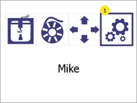 |
| 2 | Open the menu Printer information and firmware updateby pressing the Information button (1). Press the Back button (2) to return to the main menu. | 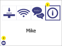 |
| 3 | The information screen shows the following (1): The printer modelThe unique name of the printer.BIOS version of the printer.Printer firmware version. Press the Back button (2) to return to the Settings to return. | 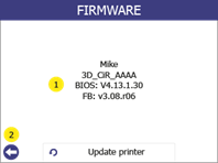 |
64.14.2 Updating the firmware
A USB stick is required to update the firmware. Transfer the update files provided by GeBioM to the root folder of a USB stick, disconnect the USB stick and then carry out the following steps:
1 | Switch on the printer. | 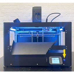 |
| 2 | Connect the USB stick to the printer. Important: The USB flash drive must be a FAT32 file format. | 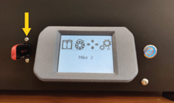 |
| 3 | Open the menu Settings (1). |  |
| 4 | Go to the menu Printer information and firmware update (1). Press the Back button (2) to return to the main menu. | 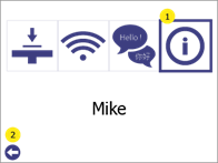 |
| 5 | Select Update printer (3). Press the Back button (2) or Cancel (1) to return to the main menu | 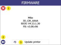 |
| 6 | Click "Yes" (1) twice to confirm this. Press "No" (2) to return to the main menu. | 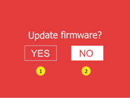 |
| 7 | Wait until the update is installed. | 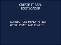  |
| 8 | Allow the printer to start, without the USB stick from the printer to remove. | 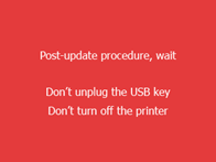 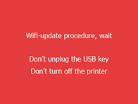 |
| 9 | Wait until a green screen with confirmation of the successful update or an ok button is displayed. Some update procedures can take up to one minute. | 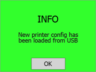 |
65.15. regular service/maintenance
To ensure that the printer continues to print as expected, regular cleaning is recommended. Both the print bed and the print head must be cleaned.
66.15.1 Cleaning the print bed
Each print leaves some oil residue from the printed material, which over time will cause printed objects to adhere less to the surface. It is recommended to clean the print surface thoroughly with isopropyl alcohol before each print to remove any oil residue (see chapter 10).
67.15.2 Cleaning the print head/nozzle
Cleaning the print head is an important process that contributes to the quality of the printed objects. It reduces the risk of clogging and ensures even extrusion of the filament.
Cleaning the nozzle from the outside
● We recommend that the outer tip of the print head (the nozzle) daily with the cleaning tool included in the accessory box.
Allow the print head to cool down first. Scrape the nozzle with the cleaning tool until the tip is free of filament residue. Make sure that you do not touch the inductive sensor (blue dot) behind the nozzle when cleaning it.
Cleaning the inside of the nozzle
● We recommend cleaning the inside of the nozzle every time a new filament spool is loaded. Only use approved cleaning filament for this process.
Proceed as follows:
1 | Open the menu Filament changeby pressing the settings button (1). | 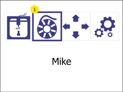 | |
| 2 | Heating up. Please wait until the target temperature has been reached. | 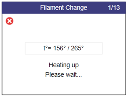 | |
| 3 | Pull the old filament out of the extruder and press the WfurtherButton (2). | 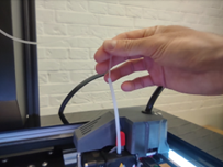 | 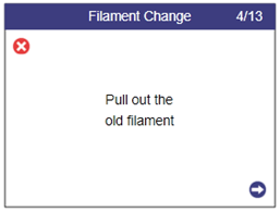 |
| 4 | Select Yes (1). |  | |
| 5 | Heating up. Please wait until the target temperature has been reached. | 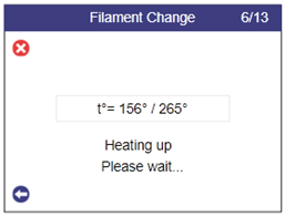 | |
| 6 | Feed the cleaning filament into the extruder. When the filament comes out of the nozzle, press the Further-button (2) | 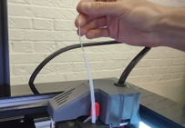 | 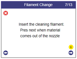 |
| 7 | In this automatic step, the temperature begins to drop as the material is extruded. Note: You may hear a clicking noise. This is normal. | 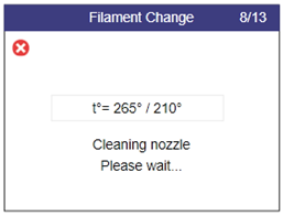 | |
| 8 | In this automatic step, the extrusion is switched off and the print head is cooled down. | 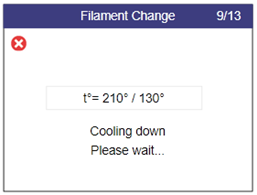 | |
| 9 | Remove the extruded filament from under the nozzle. | 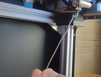 | |
| 10 | Turn the lever to idle / position 0 (anti-clockwise). |  | |
| 11 | Grasp the cleaning filament and pull it out of the extruder. | 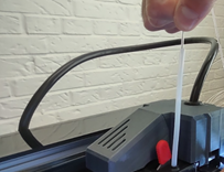 | 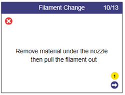 |
| 12 | Clean any burnt residue from the nozzle using the brush supplied. Attention! The nozzle temperature is 110 degrees! | 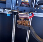 | |
| 13 | Look through the nozzle. You should be able to see through the hole. |  | 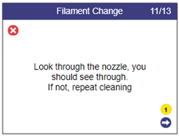 |
| 14 | Turn the lever clockwise to position 3 and then insert new filament. |  | 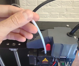 |
| 15 | Wait until the print head has heated up. | 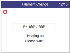 | |
| 16 | Insert the regular filament and when the material comes out of the nozzle, press the confirmation button (1) to complete the process. | 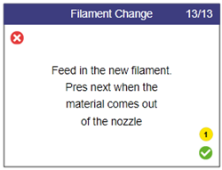 |
68.16. troubleshooting
1.
Each problem is shown with possible causes and their solution. Go through the list in the order shown. If a problem cannot be solved, contact support.
69.16.1 Printed object does not stick to the printing surface
- The print surface is not clean. Wipe the print surface with isopropyl alcohol (see chapter 14).
- The print height is incorrect. Calibrate the height by following the print bed calibration (see chapter 8).
70.16.2 Printer does not extrude correctly
- The print bed is too close to the print head during the first printed layer. Calibrate the height by following the print bed calibration (see chapter 8).
- The printer has run out of filament.
- The filament has become entangled in the filament chamber. Check the filament in the filament chamber.
- The filament is stuck in the print head. Use the filament replacement procedure (see chapter 7) to remove the filament, cut off a piece and reinsert it.
- The print head is clogged and the print head needs to be cleaned. Carry out a cleaning process (see section 14.2).
- The printed part has a rough surface with small bubbles. This can happen if the filament is damp because the filament chamber is OFF or it has been stored in an uncontrolled environment.
- Check whether the filament chamber is connected.
- Replace the filament with a filament that has been stored in a dry and warm environment.
- Leave the wet filament in the (heated) filament chamber for at least one day without printing to dry it.
71.16.3 Object not completely or not properly printed
- The filament was empty before printing could be completed. Check whether the filament needs to be replaced.
- Printer firmware error. Check the printer screen for error messages. If the error message is not self-explanatory, contact support.
- During the printing process, there was something in the work area that was blocking the printer. Check the work area for foreign objects.
- The silicone sleeve of the print head has fallen off and is blocking the printer. Check that the red silicone sleeve is correctly attached to the print head. Make sure that the silicone sleeve is not cracked.
- The power supply to the printer was interrupted during the printing process. Check whether the printer is switched on.
72.16.4 Print head does not extrude and you hear clicking noises
In some cases, the filament can get stuck in the sprockets. If the regular filament change does not help, proceed as follows:
1 | Turn the lever to idle / position 0 (anti-clockwise). | 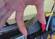 |
| 2 | Open the menu Manual controlby pressing the manual control button (1). |  |
| 3 | Start manual heating with the temperatures (5 and 6). | 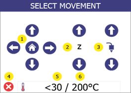 |
| 4 | Use the arrow buttons (1 and 4) to set the target temperature to 265°C and press Confirm (7) Then go back to the menu Manual controlby pressing "Back" (5). | 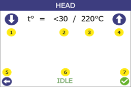 |
| 5 | Press and hold the up arrow of the extruder (3) for 5 seconds while pulling. Then press and hold the down arrow of the extruder (3) while continuing to pull. The filament should come out after 5-10 seconds. | 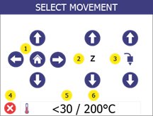 |
| 6 | Cut off the deformed piece of filament. Set the lever back to position "3". Call up the menu Filament change and follow the instructions to insert the filament. | 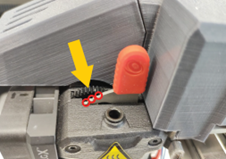 |
If the filament comes out but clogs again after another print attempt, clean the print head.
If the solution does not help and the filament is still stuck, contact cubix@gebiom.com.
73.16.5 Error messages
Below you will find all error messages where you can take action yourself. For all other error messages, please contact our support (cubix@gebiom.com).
| Error | Cause | Solution |
| ERROR 211: USB removed | USB stick was disconnected during the print job. | Make sure that the USB stick has not been removed during the printing process If the error occurs and the USB stick is still in the printer, 1. check your USB stick. 2. use a different USB stick. |
| ERROR 212: File not found | The printer is trying to resume a paused print, but the file cannot be found on the USB stick. | Restart the print job. |
| ERROR 213: USB Power Fault | The USB stick used draws too much power and has been disconnected so as not to damage the printer electronics. | Remove the USB stick; then click OK and try another USB stick. |
| ERROR 410: Setup file not found | During setup, the printer cannot find the file in the root directory of the USB stick or cannot open/read it. | Make sure that the file wifi_config.cir is located in the root directory of the USB stick. Make sure that the file wifi_config.cir is not write-protected. |
| ERROR 411: Wifi connection impossible | WiFi connection timeout (probably because the router is not responding to the printer). | Try to connect again and make sure that the WiFi router is working properly. Make sure that the firewall is not blocking the IP address of the printer. |
| ERROR 412: Wifi connection impossible | The password you entered is incorrect. | Make sure that the USB stick contains the file wifi_config.cir with the correct password for the selected network. |
| ERROR 413: Wifi connection impossible | The printer cannot find the network. | Make sure that the USB stick contains the file wifi_config.cir with the correct network name. Make sure that the WiFi router is working properly and that the firewall is not blocking the printer's IP address. |
| ERROR 417: Wifi connection lost | Wifi connection lost (timeout) | Restart the WiFi transmissionCheck that the WiFi router is working properlyTry moving the printer closer to the router. |
| ERROR 520: Newer slicer required | The version of the slicer that generated the file is old and is not supported by the current firmware | Make sure that you are using the latest version of the slicer. |
| Other errors | An error has been detected that requires maintenance. | Try restarting the printer. If the problem persists, contact support (cubix@gebiom.com) and inform them of the error code. |
74.17 Technical data
| Performance requirements | 230V AC 50 Hz (1.5A); 120V AC 60 Hz (3A) |
| Power consumption | Normal operation: < 100W Idle mode: < 50W Stand-by: < 40W |
| Operating room temperature | 5-35 °C (40-95 °F) |
| Print head temperature | Operation: 240-260 °C (464-500 °F); Maximum: 285 °C (545 °F) |
| Filament chamber temperature | Operation: 35-45 °C (95-113 °F) Maximum: 80 °C (176 °F) |
| Size of the printer workspace (Largest printable object) | W / D / H 39 / 14.5 / 14.5 cm (15.4 / 5.7 / 5.7 inches) |
| Printer size (cable and filament chamber installed) | W / D / H 67 / 54 / 75 cm (26.4 / 21.5 / 29.5 inches) |
| Printer weight | 37.5 kg (86 lbs) |