1.Before the scan
In order to obtain an optimal scan, you should consider a few things before you carry out the first scan.
1.1.Lighting
Observe the following rules:
- Avoid scattered light as far as possible
- Choose a location without direct sunlight
- Avoid light sources directly above the scanner
- If necessary, darken the room with a curtain or blinds during the scan
- If the dots above are not possible for you, darken the scanner with a dark cloth (black/dark blue)
1.2.Driver settings
You can access the settings by clicking on "Settings ..." click.
We recommend the following settings for the scan:
- Type: RGB colours (24 bit)
- Resolution: 150 dpi
- Paper size: A3
- Attribute: Colour
- Rotate: If required, this option can be used to rotate the scan by 180°.
Please note that due to an error in the scanner software, the values can only be changed using the arrow keys. If you have changed any other values, you can change them under https://gpsupport.de/faqs/so-richten-sie-ihren-microtek-scanner-fuer-eine-optimale-messung-ein/ view.
2.During the scan
2.1.Clothing
If clothing is included in the image during the scan, this will lead to problems later on. Tight-fitting clothing often does not cause any problems. In any case, avoid placing clothing on the scanner.
- Roll up the customer's trousers during the scan.
- Pin up long skirts with clothes pegs during the scan, or ask your customer to hold the skirt up.
- The scanner only captures an area close to the glass pane. You can also ask your customers to enter the scanner in their underwear. The area above the feet is not visible on the finished scan.
2.2.Position of the customer
The customer should keep the following things in mind while the scanning process is running.
- The feet should not touch each other during the scan.
- The edge of the scanable area should not be exceeded.
- If possible, the customer should stand on the scanner so that you can get an impression of what the foot looks like under load.
- If both feet cannot be scanned at the same time, the feet can be scanned by selecting the correct side "Links„/“Right" and click on "Scan page" can be scanned individually.
3.After the scan
3.1.Outline
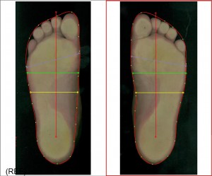
The outline should be automatically placed around the foot by the GP Manager. It should be as close as possible to the scanned foot without any part of the foot lying outside the line.
- If the line is not set correctly, follow point 3.2 (Limiting)
- If the line is not optimal, change the threshold value by clicking in the grey area to the right/left of the red line.
- Adjust the outline manually by clicking and dragging the points with CTRL + left mouse button.
3.2.Limit
If the automatic framing of the foot does not work, try the following:
- Click on "Limit„
- Hold down the left mouse button and drag a frame around the unrecognised foot. Repeat this until the frame encloses the entire foot.
- Click on "Limit" again to cut out the part you have marked.
- Try again to obtain an outline (see 3.1)
3.3.When limiting does not help
- Make sure that the background around the foot is dark/black.
- Check whether under "Processing" the tick at "Invert" is set.
- If the background is light/white, you may be using a third-party scanner that uses a CCIS sensor. These are not supported by the GP Manager.
3.4.Set bale size and foot axis
If you want to use the scan in InsoleCAD, remember to adjust the ball of the foot dimensions if necessary. You should also readjust the line for the foot axis if necessary. Then click on "Set foot axis vertical"
3.5.Set further dimensions
If you do not use the bale dimension, remember to set the other dimensions in the scan.
If you want to display further dimensions or hide dimensions, read https://gpsupport.de/faqs/wie-kann-ich-linien-bei-2d-scans-ausschalten-oder-hinzufuegen/
3.6.Finish processing
If you click on "Finish processing", the scan can no longer be edited later. This option is obsolete and should no longer be used.


