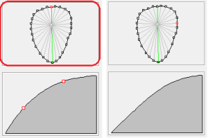
Lines selection box
In this box, you can mark the points of a selected point model with a simple mouse click. The rise of the line to the centre now appears in the rise view.

Figure 29: Left: The line selection box is outlined in red, the top point (red) is selected. The green line to the centre point is shown in the ascent view. Right: The right-hand point (red) is selected, the grey line to the centre point is shown in the ascent view. As the rise is between two green lines, it is calculated from the rise of both green lines.
By double-clicking on a point in the selection box, the grey line is coloured green and released for editing in the ascent view. Two red squares are now displayed in the ascent view. These represent points on the slope curve; the slope can be changed by moving them. The more lines you release for editing, the finer you can model your model. In practice, however, it has proven to be best to edit as few lines as possible. It is usually sufficient to edit 4-5 lines.
GP InsoleCAD calculates the rise for the grey lines between the green lines in such a way that there is a smooth transition from one modelled rise to the next modelled rise. You can see this if you mark the points between two green lines one after the other and observe the changes in the rise view.
NoteTo practise, find a point model and select a height for the model that is too high (e.g. 10 mm). You can then better observe the changes to the model in views A, I, H and V.
| Key combination | Amendment |
| Left mouse button | Select a point and view the ascent |
| left double click | Selection of a point and the ascent for editing |