GP Foot Scan
If the scanner takes a very long time after clicking on scan, this may be due to the following reasons:
The scanner remains connected to the power supply at all times.
Solution: disconnect the scanner from the power supply overnight and only switch it on after the computer has started up
The USB cable is too long.
Solution: From 1.50 m, an active USB extension should be used.
Problems with the USB port or with the USB controller.
Solution: Try a different USB port.
The wrong power supply unit is being used.
Solution: The scanner can only generate the required luminosity with the power supply unit supplied.
The wrong driver is being used.
Solution: Install the latest manufacturer drivers or try the Wia driver.
If no solution fits, please try the scanner on another computer.
If this still does not work, please contact our support by telephone.
So that not everything outside the outline is cut off, we display the image transparently one centimetre around the line.
The settings for this can be found in:
\GpSystem\GpSystem_Einzelplatz\GP_SCAN_FUSSMESS.ini
[Print]
I_Prints_Margin = 10 (the number corresponds to the width of the transparent area in mm)
Error description
A scan has been carried out with TrittScan or FußScan. However, no image appears in the GP Manager.
Causes of errors
This is often due to incorrect settings in the scanner driver. With TrittScan it can also happen that the "Limit" function must first be used or that the threshold value must first be changed.
Troubleshooting
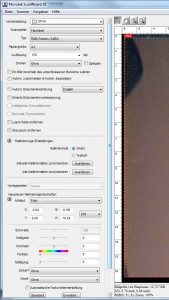
Select the correct settings for your scanner. Follow the steps under "How to set up your Microtek scanner for optimal measurement" button. For TrittScan, follow the steps under "How can I scan a tread foam with a 2D scanner?" from
Error description
The scanner scans an image, but the image only shows part of it or the colours are not correct. For example, the image is only black and white or you can only see a section of the scannable area.
Cause of error
The scanner driver only allows you to mark a part for scanning. The scanner can also only produce black and white or greyscale images. If the settings are changed, these settings are then retained.
Troubleshooting
- Ensure that the cable is correctly connected, undamaged and plugged into a USB 2.0 socket.
- Start the GP Manager
- Select "Trade fairs“ -> „GP foot measurement„
- Select on the right "Settings„
- Set the recommended Settings in.
Error description
It is not possible to create a 2D scan with the GP Manager, as after clicking on Scan page/Scan both the scanning process does not start.
Or the scanned image is not displayed correctly (black/white), or the foot outline is no longer recognised.
Causes of errors
The error can occur for various reasons. Examples of why this error occurs are
- Windows cannot wake the scanner from sleep mode, therefore the scanner is not recognised by Windows
- A file required by the driver is damaged or the driver is not installed.
- The scanner is not properly connected to the computer or the power supply.
- The settings for the scanner have not been selected correctly.
- An incorrect power supply unit is being used for the scanner.
Troubleshooting
- Make sure that the scanner is connected to the computerand the cable is not damaged.
- Check whether the power supply unit belongs to the scanner. Make sure that the power supply unit is correctly connected to the scanner
- Is the scanner connected correctly:
- Switch off the scanner (if possible) on the device. If this is not possible, unplug the power supply unit.
- Unplug the USB cable from the computer.
- Switch the scanner back on/plug the power supply unit back in
- Plug the USB cable back into the computer.
- Start the GP Manager, select a customer and then the GP foot measurement module.
- Make sure that FootScan (for feet) or StepScan (for footprints) is selected.
- Check whether the scanner is working. Select "Scan both" and wait at least 30 seconds to see if the scanner scans an image.
- If an image has been scanned but the GP Manager does not recognise the border or the image does not look as expected, read on:
- In some cases, Windows changes the name of the scanner. If the scanner is stored with the name in the GP Manager and the display of the selection boxes is deactivated, the scanner is no longer displayed. In this case, follow the instructions in the IT manual for setting up a single workstation (Set up 2D scanner) or contact the GeBioM mbH support.
General advice
To avoid mistakes in the future, the following procedures can help:
- To avoid this error in the future "Deactivate selective USB energy saving" can be deactivated.
- Disconnect the computer and scanner from the power supply overnight/switch them off in the evening.
Error description
Normally, a scanned foot is automatically outlined with a red line. The line no longer appears. However, the foot is not recognised by the GP Manager during the measurement.
Cause of error
This error can have several causes.
- You want to scan a footprint, or you have scanned a footprint and want to scan a foot, now you need to change the setting for invert.
- The scan is not so good, so that an artefact is detected in the image to the border.
- You are using a scanner that is not from GeBioM and works with a CCID chip instead of a CMOS chip
Troubleshooting
Use the "Limit" function
- Start the GP Manager and search for the customer
- Select the measurement in which the feet are not recognised
- Click on the "Limit" Button

- Draw a rectangle around the foot that is not recognised. If you have selected a rectangle that is too small, drag another rectangle until the entire foot is inside the rectangle.
- Then click on Limit again.

- Then change the threshold value setting to obtain an outline.
Deactivate Invert.
- Start the GP Manager
- Select Trade fairs -> GP foot measurement
- Select Process
- Remove the tick from Invert

The border is set at the edge of the scan
It is often the case that the border for the foot is set similarly to the following image.

- In this case, select "Settings„
- In the dialogue, set the scan area so that the edge is not scanned. Then scan the foot again.
- The GP Manager should now set the border around the foot correctly again.
You are using a CCIS scanner
- If you are using a CCIS scanner, the background around the foot is white. A CMOS scanner displays the area around the foot in dark/black.
- Unfortunately, CCIS scanners are not yet compatible with the GP Manager.
Error description
The GP Foot Measurement module displays various lines that are not required. For example, a blue outline and various straight coloured lines.
Causes of errors
The lines are various auxiliary lines that can be activated or deactivated in the settings.
Troubleshooting
You can switch all lines on/off and change the colour of all lines except the blue of the reference line.
Start the GP Manager
- For GP Manager version 6, select "Extras“ -> „Settings„
- For GP Manager version 7, select the "GP Admin“ -> „INI settings„
- In the drop-down menu, select the item "GP_SCAN_FUSSMESS„.

- You can see the individual sections of the INI file in the lower part of the dialogue. All relevant values relating to the display of the measurement can be found under "Mass„.
- Double-click on Mass, then all values of the section are displayed.

- For each line that is displayed, there are two values under mass. In each case, a value marked with "B_Use_" and a second value beginning with "RGB_" begins.
- Click on the value you wish to change. It is generally recommended that you enter a new value in the "Info" changes (see image below). The first part of the value indicates what values are possible.
B_UseYes/No, this value can be changed by clicking on the box in front of Yes. If the value is "No", the corresponding line is not displayed. RGB_Red/yellow/blue Value for displaying the line colour. The value can be set using the "Change" button can be customised.
Attention:
The GP Manager must be restarted for changes to take effect. - If you are not sure which line you want to deactivate, you can first select the corresponding "RGB_" value. You can then change the value for the corresponding line. Remember that changes are only applied after restarting the GP Manager.
Error description
After clicking on 1:1, the model is not displayed in the correct size on the monitor.
Causes of errors
The GP Manager is not calibrated for the monitor.
Troubleshooting
Version 7
- Start the GP Manager.
- Select "GP Admin“
- Select "Calibrate screen“
- Drag the window at one corner so that it is displayed 10 x 10 cm on the monitor

Note:
If you use several monitor models, a 1:1 display is only guaranteed on the monitor on which the calibration was carried out. - Click on "Apply calibration„
Version 6.5
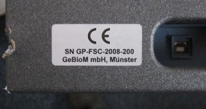
You can see which scanner you have by looking at the serial number. On the scanners we supply, the serial number is always located where the power and USB cable are connected to the scanner.
After the last letter/number of the serial number you can recognise which scanner it is, the following endings are possible:
S: It is a Microtek scanner with one tube
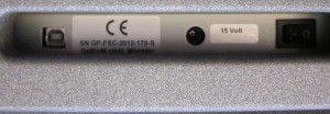
S2: It is a Microtek scanner with an LED
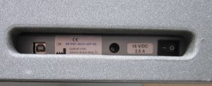
P: If the serial number ends in P, it is a Plustek scanner
Number: If the serial number ends with a number, it is a Mustek scanner.
Error description
The scanner is only displayed as a USB device in Windows Device Manager. An attempt to update the driver fails.
Causes of errors
The error occurs if the USB cable is too long or defective and if the scanner is connected to a USB hub.
Troubleshooting
In general, the scanners should not be connected to a passive USB hub (passive means that the hub does not have its own power supply). This often leads to errors. Try connecting the scanner directly to the computer via a USB cable. Then try to install the driver for the scanner again.


