In the print page editor, you have the option of specifying a fixed printer for any print page. To do this, the page must be selected and then the printer must be specified using the Format button.

Example: A printer can be created several times with different settings via Windows and then permanently stored in the corresponding print file.

The measurement is generally displayed and viewed from the heel at the bottom to the toes at the top. If this display is incorrect, it can be rotated via an ini entry.

\GPSystem\GpSystem_single_seat
DV_MultiSens_PSAABT.INI
I_degree = 180 //0, 90, 180, 270, 360

I_degree can now be changed in a clockwise direction (ascending to the right, descending to the left).

If there are several individual workstations (profiles) in the GPSystem folder, you can find the correct individual workstation by right-clicking on the desktop shortcut and selecting Properties in the Target section.

...\GpSystem\GpSystem_Name_for_the_single_seat

praxis.ini / from version 7.3: GP_TC_Einlagen.ini

[INSERT]
B_UseMaxU18 = yes //a general discount is used
F_MAXU18 = 15.00 //this is the maximum amount for children

We recommend assigning a separate prefix to each branch with a separate database so that customer numbers are not assigned twice. The settings can be found here:

GPM_V7\GpSystem\GpSystem_Single_user\Gpman.ini

[Database]
T_Prefix = ihr_Prefix //The GP Manager automatically increments the numbers after the text

You can see which file is responsible for the scan settings in the ;
GP_TC_2DScan.ini

[MESSEN]
B_rotateFScan180 = no //the measurement is rotated by 180 degrees
FILE_TWAIN = Config_TWAIN_Filiale //further scan settings

Config_TWAIN_Branch

[TWAIN]
T_Scanner = Microtek ScanWizard DI //Name of the scanner from the scanner list
B_Select = yes //if the specified scanner name is not found, a selection dialogue appears
B_Unbedingt_Dialog_Aufrufen = yes //yes= a scan dialogue is displayed before the scan
B_Erzeuge_ScannerListe = yes //Creates a scanner list in C:\Temp\GpTemp > TWAIN_Liste.txt
B_Create_TWAIN_Property_list = no


If scans are displayed rotated or mirrored, they can be rotated by 180 degrees in praxis.ini or adjusted via the scanner software (B_Unbedingt_Dialog_Aufrufen = yes).


The selection of employees can be created separately for each profile or each individual workstation. The settings for this can be found in the

GPM_V7\GPSystem\GPSystem_Filiale_xyz\Praxis.ini and from version 7.3 in GP_TP_FILIALE.ini

[EDITOR]
i_anz = 2 // Number must match the number of editors
B_AUTOEDITLIST = yes //yes = list is automatically created and dynamically expanded > every new employee is saved - no = only one of the stored employees can be selected
T_BEARBEITER_1 = Name or abbreviation of the employee
T_PROCESSOR_2 = MK

  1. In the GP Manager, open the module "GP FussMess"
  2. In the selection box on the right, select "KinectScan" as the desired
    Scan method
  3. To scan feet, select "Scan side" and then "Scan plaster"
  4. Position the patient's leg so that it is as still as possible and there are no obstructing objects in the way.
  5. If you need to support your leg, place a support as close to the knee as possible.
  6. You should be able to move freely within an area of approx. 50-100 cm around the foot.
  7. As a starting position for the measurement, we recommend viewing the foot and lower leg from the medial/lateral side in the live image. Ensure that the camera is aligned parallel to the leg.
  8. Start measurement with the SHIFT key
  9. Now move calmly and evenly around the foot:

10. make sure that the camera is focussed on the foot at all times and that the distance between the leg and the camera always remains the same.

As soon as the foot is no longer in the focus of the camera, the scan is automatically cancelled and you have to start again

11 When you have captured the foot from all perspectives, you can pan the camera to the site and end the measurement with the CTRL key

12. click on "Apply"

13 Now you must align the measurement

14 To do this, move the red dots in the view:

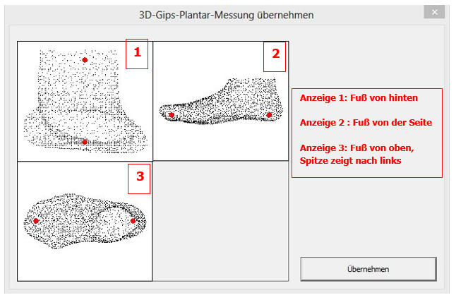
15 In the following window you can define the cutting lines: the upper red line determines where the measurement is cut off, the lower red line determines the division of the foot and lower leg and should be positioned approximately at the height of the ankle

Possible errors:

  • Distance between the camera and the foot is not correct
  • Interfering objects in the scan area