Error description

If a scan is created with the Kinect in the GP Podiatry module, the following error message appears: "3D back scanner ABW measurement could not be loaded! For more information, see TEMP/PodoScan/ABW.TXT"

Kinect

Causes of errors

The Kinect expects an object in a certain area in front of the scanner. If the area in front of the Kinect is free, the error is generated.

Troubleshooting

Position your patient so that they are within 40 - 100 cm of the Kinect. Then start the scan again. The error should not appear again.


If the error occurs again when scanning again, contact GeBioM Support.

If you want to use a different tool for your router or replace a tool, there are a few things you need to bear in mind.

  • ATTENTION:
    Before installing the new tool, completely loosen the union nut of the chuck once. Clean the chuck and the motor shaft. Degrease the chuck and the tool with acetone before installation.
    If the chuck is dirty, the tool may come loose. This can result in damage to the milling table.
  • After changing the tool, you must reset the zero point of the milling machine in the GP Manager. How you set the zero point depends on the type of milling machine you have. You can refer to Youtube For most milling machines, watch a video explaining how to set the zero point.
  • In rare cases, you may want to use a tool with a different diameter. In this case, you must enter the diameter in the INI file for your milling cutter under ".\GpSystem\Fraese", the folder is a subfolder of the GP Manager (How to find your GP Manager installation).
  • You must then recreate any existing milling files. The milling files still contain the old values for diameter and zero point. If you use these, the insert will not be milled correctly.
  • When buying a tool, you should pay attention to the direction of rotation of the tool. If you purchase tools from us, you will always get the correct direction of rotation.

If this has not helped, you are welcome to contact GeBioM Support.

Error description

After starting the GP Manager, a series of similar error messages of the form "Cannot load XY.dll" appear

Depending on the installation of the GP Manager, various DLL files are listed, for example:

  • GP_DV_Fussdruck.dll
  • GP_CAD.dll
  • GP_Questions.dll

Causes of errors

A DirectX version is required to start the GP Manager. If DirectX is not installed, the GP Manager lacks information on how it should display individual modules.

Troubleshooting

Install DirectX, the installation file is supplied with the GP Manager and can be found in the GpTools folder.

  • Open the folder in which the GP Manager is installed (To find the GP Manager folder).
  • Open the GpTools Folder
  • Go to the Directx Folder
    • If the computer has an Internet connection, start dxwebsetup.exe
    • If the computer has no Internet, you can run directx_Jun2010-redist.exe

If the error persists, please contact GeBioM Support.

Error description

After starting the GP Manager, the error message "Mfc100.dll not found" appears.

Causes of errors

The file is part of the Visual Studio redistributable pack (vcredis), the most common cause is that it is not installed on the computer.

Other possibilities are that the file has been corrupted or deleted.

Troubleshooting

The installation programmes for this are delivered together with the GP Manager and can be found in the GpTools subfolder.

  • Open the folder in which the GP Manager is installed (How to find the directory).
  • Open the folder GpTools Folder.
  • As the packages are not cumulative, you must ensure that all packages have been installed. Execute the installation programmes from the folders one after the other.
    • Vcredist_2008_SP1\vcredist_x86.exe
    • Vcredist_2010\vcredist_x86.exe
    • Vcredist_2013\vcredist_x86.exe
  • Restart the GP Manager.

If the problem persists, please contact GeBioM Support.

Error description

After clicking on 1:1, the model is not displayed in the correct size on the monitor.

Causes of errors

The GP Manager is not calibrated for the monitor.

Troubleshooting

Version 7

  1. Start the GP Manager.
  2. Select "GP Admin
    GP-Admin-Symbol
  3. Select "Calibrate screen
    Bildschirm-kalibrieren-Symbol
  4. Drag the window at one corner so that it is displayed 10 x 10 cm on the monitor
    Kalibrierfenster-Version-6.5-Cursor-markiert

    Note:
    If you use several monitor models, a 1:1 display is only guaranteed on the monitor on which the calibration was carried out.

  5. Click on "Apply calibration

Version 6.5

  1. Start the GP Manager.
  2. Select "Extras" -> "Calibrate screen ...
    Menü-Extras-Bildschirm-kalibrieren-markiert
  3. Follow the points above from point 4.

Error description

The error occurs when trying to mill a file:

Fehler-WIBU-Box-lite-USB-BusError "Origin: CNC interpreter, no USB stick (WIBU-Box lite) with isel company code detected on the USB bus; programme processing only possible without commissioning the motion control (MCTL).

Causes of errors

The milling file has the wrong file extension. The error occurs if the file has the file extension CNC. In the illustration above "moulding.cnc"

Troubleshooting

Change the file extension to NCP, for the above case from "mouldings.cnc" ->"mouldings.ncp

  • Open the folder where the file is located.

    Dateiendung-ausgeblendet

    Figure 1: File extension is hidden in Explorer

  • If the file extension is not displayed (see Figure 1), proceed as follows:
  • Select "Organise" -> "Order and search options
    Ordner-Suchoptionen-markiert

    Figure 2: Folder and search options


  • Deactivate the tick next to "Hide extensions for known file types
  • The file extension is then displayed in Explorer (see Figure 2). Rename the file extension to "ncp" (for the example "mouldings.cnc" -> "mouldings.ncp„).

    Erweiterungen-ausblenden-deaktiviert-markiert

    Figure 3: Display file extensions.

If you do not want to use uEye cameras, please note the following:

  • Officially, GeBioM only supports uEye cameras.

Camcorder

  • Modern camcorders generally do not provide a live image. This means that you cannot use them.
  • Older camcorders often have a Firewire interface that provides a live image. If you want to use the interface, the same requirements apply for the data bus as for the USB bus on uEye cameras (What are the system requirements for GP VideoSupport II?).

Webcams

  • If you want to use a webcam, please note that the exposure time can be adjusted.
  • If the individual images are blurred, change the exposure time
  • If you want to measure angles with webcams, the angles are often distorted due to the lens in the outer areas.

We recommend for operation with GP VideoSupport II uEye cameras. These cameras make it possible to use different lenses. In addition, these cameras offer high-contrast images with short exposure times. This is particularly important if movements are to be recorded without motion blur.

If you want to use other cameras read "GP VideoSupport II with non-uEye cameras„.

As the uEye cameras transfer a large volume of data to the PC, the computer must have sufficient USB 3.0 ports (Please note that there are differences between USB ports. The older standard is USB 2.0, these ports are usually black. Ports that support the newer USB 3.0 standard are blue).

We recommend the following minimum requirements for a computer:

Minimum requirement
CPU/processor Intel Core i7 - 3770K with 4×3.5GHz
Working memory 8192Mb DDR3
Fixed plates 1 TB
Graphics card 1024 MB GeForce GTX 650
USB 4xUSB 2.0/2xUSB 3.0
Mainbaord Asus P8Z77-V LX
Network 10/100/1000 MBit LAN, DSL capable

The USB ports integrated on the mainboard usually share a data bus and therefore the bandwidth of the data bus. Whether all USB ports integrated on the mainboard use the same data bus or are connected to several data buses depends on the mainboard. This can be looked up in the manual of the respective mainboard or asked the mainboard manufacturer.

Mainboard-Erweitereungskarten

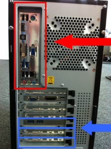
Figure 1: red: Connectors on the mainboard blue: Expansion cards

We recommend operating each uEye camera on its own data bus. To realise this, a USB 3.0 expansion card must be installed for each connected uEye camera (see Figure 1).

Error description

The 3D plaster model is "frayed" at the leg opening.

Gips-markiert

Causes of errors

The opening of the plaster was not closed during scanning.

Troubleshooting

  • Make sure that the plaster has a closed surface during scanning.
  • Fill the plaster with crumpled paper or cover the opening with adhesive tape during the scan

Error description

You would like to insert a measurement in a CAD module. If you are in a CAD module, there is a "Measurement" button in the toolbar at the top left, clicking on the button does nothing, or only the blue line in CAD is shown/hidden.

Troubleshooting

  • Hold down the CTRL key and click with the left mouse button on the "Trade fairs" Button
    Ansichten-Messung-markiert-V7
  • A dialogue appears in which you can select a measurement. Make sure you select a measurement that was taken with the correct measuring device (2D Scan, 3D Scan, KinectScan).
  • The CAD measurement should then be used.
  • If the desired measurement is not displayed in GP Manager version 6, make sure that "All data records" is selected.