Error description

The milling machine itself has power, but the computer of the milling machine cannot be switched on. Nothing happens when the switch is pressed to switch it on.

Cause of error

With older milling machines, the switch for switching on the computer may be defective.

Troubleshooting

  1. First make sure that the computer of the milling machine is really not switched on.
  2. Pay attention to the two LEDs next to the USB ports on the front of the router. One LED indicates whether the router's computer is switched on, the second indicates whether the computer's hard drive is working. The LEDs should not light up.
  3. If one of the LEDs lights up, the computer is switched on. In this case, contact GeBioM Support.
  4. Switch on the computer and check whether the LEDs light up. If the LEDs do not light up, the switch is probably defective.
  5. Remove the switch by inserting a sturdy, flat tool (small screwdriver, spatula, etc.) between the switch and the housing of the router from above. Carefully lever the switch out of the housing. If the switch has been pushed out a little, you can also start at the bottom.
  6. Once you have removed the switch from the housing, you should see two cables attached to the switch. The cables are not live, so you can handle them safely.
  7. If the cables are insulated up to the switch, remove a little of the insulation from both cables (as close as possible to the switch). Then use a conductive object (screwdriver, knife, etc.) and short-circuit the cables for a brief moment.
  8. Pay attention to the LEDs, if they light up now, the switch is defective. The computer should start and you can work with the router. You can switch the computer on and off by short-circuiting the switch as described in point 7; it is best to leave the switch hanging out of the housing by the cables until it has been repaired.
  9. Contact GeBioM Support so that they can repair the switch.


Error description

You want to create a milling file in CAD and transfer it to the milling machine using a data carrier rather than via the network.

Troubleshooting

To transfer the file to the milling machine, you need to know two folders.

  1. The folder in which the file created in CAD is saved.
  2. The folder in which the milling machine searches for the file.
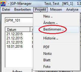
  • Open the GP Manager where you created the insert with CAD. Select the customer for whom you want to create a CAD file via "Project" -> "Determine ...„.
    GP-Manager-Projekt-Bestimmen-markiert
  • Select a CAD model in the project view by double-clicking on it, or start the CAD module via "Analysis" -> "CAD
  • Click on "Milling".
    GP-Manager-GP-Fräse-Fräsen-markiert
  • Start the GP tiller module via "Analysis" -> "GP milling machine
  • Above you can see the folders in which GP CAD saves the milling file and the folder in which the finished milling file is saved.
  • Select the model you want to mill from the job list.
  • Click on "Create milling file", the milling file should now be stored in the output folder. You can copy this to a data carrier and transfer it to the milling machine.
    GP-Manager-GP-Fräse-Ordner-Markiert

The second folder you need to know is the folder in which the milling machine searches for the milling file. How you find this folder depends on the milling machine. Copy the file from the data carrier to the corresponding folder on the milling machine.


Error description

The GP Foot Measurement module displays various lines that are not required. For example, a blue outline and various straight coloured lines.

Causes of errors

The lines are various auxiliary lines that can be activated or deactivated in the settings.

Troubleshooting

You can switch all lines on/off and change the colour of all lines except the blue of the reference line.

Start the GP Manager

  • For GP Manager version 6, select "Extras" -> "Settings
  • For GP Manager version 7, select the "GP Admin" -> "INI settings
  1. In the drop-down menu, select the item "GP_SCAN_FUSSMESS„.

    INI-Einstellungen-GP_SCAN_FUSSMESS-markiert
  2. You can see the individual sections of the INI file in the lower part of the dialogue. All relevant values relating to the display of the measurement can be found under "Mass„.
  3. Double-click on Mass, then all values of the section are displayed.INI-Einstellungen-Masse-markiert
  4. For each line that is displayed, there are two values under mass. In each case, a value marked with "B_Use_" and a second value beginning with "RGB_" begins.
  5. Click on the value you wish to change. It is generally recommended that you enter a new value in the "Info" changes (see image below). The first part of the value indicates what values are possible.
    B_UseYes/No, this value can be changed by clicking on the box in front of Yes. If the value is "No", the corresponding line is not displayed.INI_Einstellungen-Ballenmass-Checkbox-markiertRGB_Red/yellow/blue Value for displaying the line colour. The value can be set using the "Change" button can be customised.INI-Einstellungen-RGB_Taillenmass-Ändern-markiert
    Attention:
    The GP Manager must be restarted for changes to take effect.
  6. If you are not sure which line you want to deactivate, you can first select the corresponding "RGB_" value. You can then change the value for the corresponding line. Remember that changes are only applied after restarting the GP Manager.

Error description

You have two or more installations of GP Manager and would like to transfer data between them.

Troubleshooting

There are several ways to share data between different installations, depending on the effort involved.

Each method has its own advantages and disadvantages. Which method is suitable for you depends, among other things, on how your company IT is organised.

Export GPF files and import them on the target computer

This method requires some manual work, but also reliably backs up the data. You can use this method to both transfer the data and perform a backup. However, the effort required increases with each additional installation.

This is a particular problem if data is collected on several computers, but needs to be available on all of them. With more than 2-3 installations, the effort involved in this case is considerable.

How to back up and restore GPF files is described here: "How can I back up the data from my GP Manager?„.

Advantages

  • If you use this method regularly, you will automatically have a data backup.
  • If the data volume is low, you can also send the data as an email.
  • With regular backups, only the newly created data needs to be backed up. A single data backup only takes a short time.

Disadvantages

  • You could also send individual data records manually by email, but this is quite time-consuming as you have to search for the relevant files using the customer number. As a result, the data is usually only available on the target system after a long delay. Depending on the frequency of the backup Daily, Weekly, ...
  • The data must be backed up on each computer on which it is recorded and, if necessary, transferred to all other computers. The effort involved increases with every computer that is added.

Using GP Manager with a server

This method is only available to you if you have also purchased the GP Manager as a server version. If the GP Manager installations can be connected via a network, you can use the method of using one installation as a server. The server manages the database with all measurements and the other GP Manager installations access it.

Advantages

  • All GP Manager installations have access to the same data.
  • Once measurements have been recorded, they are immediately available to all installations.
  • Once set up, this method requires hardly any manual intervention.
  • Ideally, only the server needs to be backed up so that all data collected with GeBioM products is backed up (this only applies if all installations are actually used exclusively in server mode).

Disadvantages

  • There should be a fast network connection between the individual installations (a local network or a fast Internet connection).
  • If the data is transferred via the Internet, a VPN server is also required, as the GP Manager requires Windows shares.
  • A computer is required as a server on which the entire system runs.
  • If the server fails, the other installations also stop working.
  • If no network connection to the server is possible, the other installations will no longer work.
  • If no data backup is performed on the server, in the worst case all data will be lost if the server loses data.

Save and open customers

You can always export individual customers via "File" -> "Save" and then import them in another installation with "File" -> "Open".

Advantages

  • The function is activated for every GP Manager installation.
  • Easy to use, once a customer has been selected, it can be saved.
  • Good control over the data that is shared.

Disadvantages

  • If several data records are to be transferred, the method is time-consuming.
  • You must transfer the measurements individually.
  • Depending on how you transfer the data, the data may not be available on the target computer until later.
  • If the data is to be available on several computers, this method is labour-intensive.

Sending data records with GP Mail

You can purchase the GP Mail module, which allows you to send customers emails directly from the GP Manager.

Advantages

  • You can select the target installation for each data record you want to send.
  • You can control very precisely which data you would like to transfer.
  • The data can be made available on the target system in a timely manner, as it can be sent quickly by email.

Disadvantages

  • You must transfer the measurements individually.
  • This method is only suitable if only a few measurements are to be divided.
  • As all customer data is sent in one email, this only works with smaller data sets. Sending videos quickly fails if the email attachment is too large
  • The data records must be imported individually on the target computer.
  • It is time-consuming to make all measurements available on all installations.

If you need advice on which method is suitable for you or how to configure the GP Manager, you are welcome to call GeBioM Support.
Error description

The brush on the router is so worn that it can no longer generate a sufficient vacuum and you want to change the brush yourself.

You need:

  • 1 x 4 mm or 5 mm HSS drill bit
  • 1 x replacement brush
  • Pop rivets (4 mm) as well as matching washers and riveting pliers
    • We strongly recommend riveting the new brush as well. The vibrations of the milling machine can cause nuts to come loose and fall into the milling machine. This can lead to damage to the tiller. If you still want to fasten the new brush with screws, do so at your own risk. In any case, make sure that you Self-locking nuts use. In addition, the screws should protrude as little as possible and have a countersunk head. You are responsible for any damage to the tiller caused by improper maintenance.
  • 1 x hacksaw or heat gun

This is how it's done:

  • Remove the brush cup from the tiller.
  • Drill into the pop rivets from the outside. Take care to minimise damage to the brush pot when drilling.
  • Cut the new brush into suitable pieces so that they fit into the brush head from the inside, or use a heat gun to mould the brush.
  • Place the new brush in the brush pot and drill the corresponding holes in the brush.
  • Place a washer around each pop rivet from the inside.
  • Pull out the mandrel of the rivet with the riveting pliers until it breaks off.


Error description

The scanner is only displayed as a USB device in Windows Device Manager. An attempt to update the driver fails.

Causes of errors

The error occurs if the USB cable is too long or defective and if the scanner is connected to a USB hub.

Troubleshooting

In general, the scanners should not be connected to a passive USB hub (passive means that the hub does not have its own power supply). This often leads to errors. Try connecting the scanner directly to the computer via a USB cable. Then try to install the driver for the scanner again.

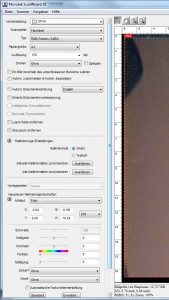
To achieve optimum results for the 2D foot scan, please use the following settings:

  1. Start the GP Manager
  2. Select a customer "Project" -> "Determine
  3. Select "Trade fairs" -> "Foot measurement
  4. Make sure that "FootScan" is selected
  5. Select "Settings ...
    1. If a selection window opens, select "Microtek ScanWizard DI (TWAIN)
    2. If a click does not produce any results, you can also change the settings directly via the ScanWizard DI. To do this, select the Start menu at the bottom left of Windows and click on "All programmes" -> "MicrotekScan Wizard DI for Windows" -> "ScanWizard DI". All changes are adopted by the GP Manager for scans.
  6. Due to an error in the scanner manufacturer's driver, the values in the menu can only be changed by :
    • The value is entered using the keypad
    • Click on the field to be changed and select the value with the arrow keys
  7. Select as Type: RGB colours (24-bit)
  8. Select as Paper size: A3
  9. Select as Resolution: 150 dpi

You can use the default settings for all other settings.

If you need the image rotated, select "Turning" the corresponding value.

If you have changed settings, you can see the settings in the screenshot. The dialogues differ depending on the version of the installed driver. Select the screenshot that corresponds to your version.

Empfohlene-Einstellungen-Microtek

Figure 1: Older driver

ScanWizdard-neu-Einstellunge-Allgemein-Standardeinstellungen-markiert

Figure 2: Recommended default settings of newer drivers

ScanWizdard-neu-Einstellunge-Vorgaben-markiert

Figure 3: Default settings "Preferences" tab

ScanWizdard-neu-Einstellunge-Bildverarbeitung-markiert

Figure 4: Standard settings "Image processing" tab


Error description

When the tiller reaches the rest position, it immediately moves to the limit switch.

Cause of error

An incorrect value has been entered when determining the zero point.

Troubleshooting

If you have determined the value for the zero point in the GP Manager, you must enter it with a minus sign. If you have changed the zero point and then this error occurs, you have probably forgotten the minus sign in front of the value. The milling machine triggers the limit switch. This is how you set the zero point correctly:

  1. Follow the instructions for determining the zero point
  2. Ensure that the remote programme is started on the milling machine and that there is a network connection between the milling computer and the computer on which the GP Manager is installed.
  3. Start the GP Manager
  4. Select "Analysis"->"GP milling machine
  5. Click on "Setting the zero point
  6. Enter the correct zero point in the dialogue that opens in the remote program.

Error description

The milling file does not arrive at the milling machine. The router is not able to find a routing file.

Cause of error

If nothing has been changed on the computers, the network connection between the milling machine and the computer is often interrupted. If the computers have been reinstalled, a path is often incorrect or a network drive is not shared.

Troubleshooting

  1. Make sure that both the computer of the router and the computer on which the GP router is running have a network connection.
  2. If necessary, restart both computers.
  3. Start the GP Manager
  4. Select "Analysis"->"Gp milling machine
    GP-Manager-Analyse-Fräse-markiert
  5. Make sure that the right-hand path specification contains the same path as in the remote programme of the milling machine under "Settings"->"Options"->"Control system". In the case of network connections, the paths may look different, but must refer to the same directory.Remote-Einstellungen-Optionen-markiert
    GP-Fräse-Dest-NCP-markiert
  6. Is in the right-hand path "C:\Temp\GpTemp", there is usually a network problem. First try to resolve the network problem. In this case, the GP Manager saves the data in the GpTemp folder as the network drive of the milling machine cannot be found.
    GP-Fräse-Dest-Temp-markiert
    Once the network connection has been re-established, you must restart the GP Manager once for it to apply the change.
    Is in the path "C:\GEBIOM_SQL\GPDATA\Fraese\CNC", there may be a problem with the INI file belonging to the milling machine. Unless the CNC Remote programme is also set to this folder.
    If you have made changes to the INI, check the INI file. If you have not made any changes and this is the wrong order, contact GeBioM Support.
    GP-Fräse-Dest-CNC-markiert
  7. If the correct path to the milling machine is entered there, open the path in the file manager (on the computer on which the GP Manager is installed) and try to create a new file. Right click->"New"->"Text document". If the file cannot be created, enter the folder on the milling machine with "Full access" for "Everyone" button. If you can then create a file from the computer on which the GP Manager is installed, milling should work. Start the GP Manager and try to transfer a milling file again.
  • Please restart the computer once before contacting support.
  • Make sure that all cables are connected to your computer.
  • Check whether your computer can access the Internet (try to load a website)
  • Have an administrator password ready in case our support team needs to connect to your computer, without administrator rights most errors cannot be rectified.
  • If the computer is not connected to the Internet, it is helpful if you can connect the computer to the Internet.
  • Make a note of the hardware versions of the GeBioM products.