• Make sure that all the latest updates are installed for your Windows 10. If you do not allow automatic updates for Windows 10, you should always install the update KB3093226, as this fixes a bug that affects the Bluetooth function.
  • If you are still using an old 2D Mustek scanner, you can no longer use it from Windows 8 onwards. Unfortunately, there is no working driver for Windows 8 and 10 to address the scanner. If you do not know which scanner you are using, read "How can I recognise which scanner I am using?„.
  • Make sure that hardware that does not originate from GeBioM is also compatible with the new Windows version.
  • After updating to Windows 10, be sure to update the Drivers for your Graphics card.
  • After the update, make sure that the DirectX version is the latest version. You can download the setup for DirectX in the subfolder \GpTools\Directx of your GP Manager (How to find your GP Manager installation). The setup file is called dxwebsetup.exe and requires an Internet connection to function.
  • Make sure that the Visual Studio Redistributable packages are installed. The packages are also located in the GpTools folder of the GP Manager installation (Vcredist_2008_SP1, Vcredist_2010, Vcredist_2013).
  • Download the latest drivers for your hardware from our homepage. With the update to Windows 10, the 2D scanners, for example, may no longer work.
  • If you do not know which scanner you are using, read on: How can I recognise which scanner I am using?

Compatibility list

This list only includes current hardware from GeBioM. For older hardware, please contact customer support to be sure.

Start GP Manager, "Analysis" -> "GP CAD" -> ">>Library" -> Group ".."

If you have already made changes to the current insert and want to assign the insert to a new group, you should first assign the insert to no group or to an existing group and save the insert. New groups are only displayed when you open the dialogue "Adding an insert to the library" has been closed once. The insert can then be opened again and assigned to the appropriate group. However, you can already create the group.

  1. Enter a unique number for the group in each line of the list, followed by an = sign and the group name.
  2. Select "Save".Dialog-Gruppe-anlegen-Speichern-markiert

Attention:
The group is not yet displayed. If you select the insert not have changed select "Back" -> "Back"
Have you changed the insert select "Back" -> adjust the other settings -> "Apply changes". A new group can only be selected the next time the insert is opened, after which the insert can be saved with the new group.

Start GP Manager, "Analysis" -> "GP CAD" -> ">>Library"

  1. Select the library from the "Library" drop-down menu in which you would like to save the insert.Dialog-Bibliothek-einpflegen-Bibliothek-markiert
  2. Select the model you want to change.

    Note:

    You can only change the supplied templates from the "KD_Einlagen" library if you save them in a separate library. To do this, you must first create a new library.Attention!
    If you select an existing model and "Apply changes", the model will be overwritten with the currently open model. If you want to change an existing model, make sure that this model is also currently loaded in InsoleCAD! "- New model -" select.
  3. Enter a name for the model under "Name" (e.g. sports insole, hollow foot insole, etc.).
  4. Select a grading table for your insole. The grading table defines the size of the insole for the different shoe sizes. If no table is offered in the drop-down menu or if you want to create your own grading table, click on "..".Dialog-Bibliothek-einpflegen-neue-Tabelle-markiert
  5. In the following dialogue, you can import the grading table of an existing insole or create a grading table yourself. This is particularly useful if you want to transfer existing blanks to your milling library and also want to use the insole moulds for your insoles. Each line of the grading table consists of a shoe size and measurements in mm (shoe size = length width height). In the table, the measurements are given in English formatting. This means that decimal places are indicated by a point. So not 10.00 mm but 10.00 mm. It is not necessary to create a separate line for each shoe size. Missing information can be entered via "Calculate" can be interpolated.Gradiertabelle-Name-Speichern-markiert
    Give the table its own name in the field to the left of Save and click on
    "Save".

    Note:
    Existing grade tables can be found in your local GP-Manager installation under: ./GpSystem/BIB_NAME/MODELLNAME.gradingyou can access these via the "Import ..." button and modify it for your purposes.
    Where NAME in the path specification stands for the name of an existing library and MODELNAME for an existing model.
  6. You can also sort the inserts in a library into groups. This helps you to find the insert in the library later. In the drop-down menu, select "Group", select the group to which you want to add the insert; you can also leave the insert out of any group "" group. If you want to create a new group (e.g. Proprio - Child), please read "Create a new last/insole group".
  7. You could add more "Info" to further describe the insole (e.g. pad 5 mm, plantar fascia long, etc.).
  8. Finally, you can choose whether you want to use the "Place the model as high up as possible", the insert is sorted as high up as possible in the quick selection, making it easier to call up the insert quickly.
  9. With "Insert model into library" button to create the insert in the library.

Error description

You have your own inserts that you use frequently and would like to find them more easily or process them more often.

Error solution

It makes sense to organise the inserts in separate libraries so that you can quickly load frequently used inserts as templates. To do this, start the GP Manager and first define a customer via "Project" -> "Determine". You now have the option of selecting an existing insole for the customer or modelling a new insole with the help of a measurement.

Then select the GP CAD module via "Analysis" -> "GP CAD". On the right are the two buttons for managing your libraries.

  • Load model from libraryAus-BIB-Suchen
  • Add model to libraryZur-BIB-hinzufügen

Toolbox-Bibleothek-markiert

Edit your insert until you want to add it to the library, click on: ">>Library"

You can manage your libraries in the following dialogue. You now have several options on how to proceed. You can Create a new library or you can use the Adding an insert to an existing library.

Start GP Manager, "Analysis" -> "GP CAD" -> ">>Library"

If you want to save the insert in a separate library, click the ".." Button behind Libraryin the following dialogue you have the option of creating a new library.

  1. To do this, enter the following in the "New name" to enter the name for the new library (e.g.: Proprio inserts, Finn inserts, Elegant, ...).Dialog-Bibliotheken-verwalten-Neuer-Name-markiert
  2. Select "Create new BIB" and click on "Back".

Libraries can also be renamed here via "Act. Rename BIB".

If you wish, you can also use existing libraries in this dialogue via "Deactivate this BIB" button. The inserts of these libraries are then no longer displayed in the quick selection in the GP CAD module. About "Integrate this BIB", deactivated libraries can be displayed again. Then follow the points under "Insert insert into existing library".

  1. Import GPF files. To do this, open the database dialogue "File" -> "DatabaseDatei-Datenbank-markiert
  2. For the field "External data" indicates the path in which you have exported the data.
  3. Select "1. copy data" and wait until the copying process is complete.

Select "3. enter data" after the process is complete, you will have restored your data.

Datei-Import-markiert

Importing for Version 7 is explained in the manual:

To import/export or save files as GPF, click on the "GP GPF" tile on the GP Manager after selecting a customer.


  1. Open file

The "Open file" tile is selected if you want to add a GPF file to the selected customer.

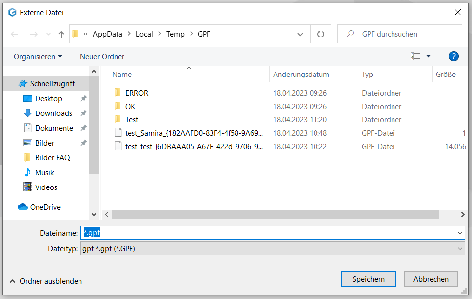
Clicking on this opens a browser window in which the corresponding file can be selected. This is done by clicking on the "Open" button.


  1. Save file


The "Save file" tile is selected if the selected customer with all measurements is to be saved as a GPF file.


This is done by simply clicking on the tile. When the file has been saved, "Written files: 1" appears in blue at the bottom centre.
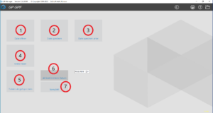
 

  1. Save file as


The "Save file as" tile is selected if the selected customer is to be saved in a different file path or if only certain measurements or designs are to be saved as a GPF file.


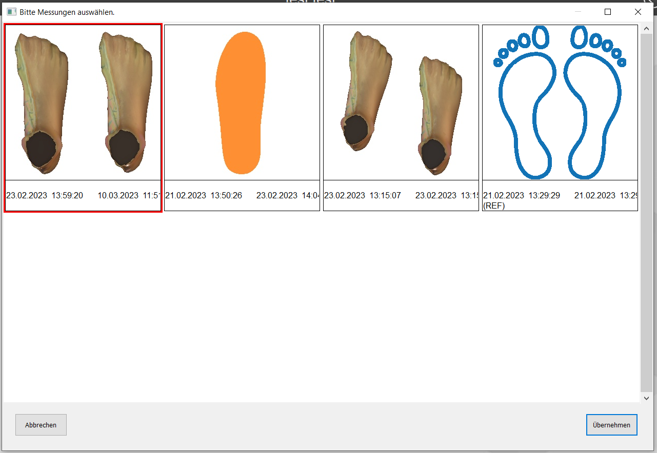
Clicking on the tile opens a window in which the measurements and constructions of the selected customer are displayed.


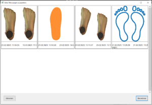
Clicking on a measurement selects it and gives it a red border.

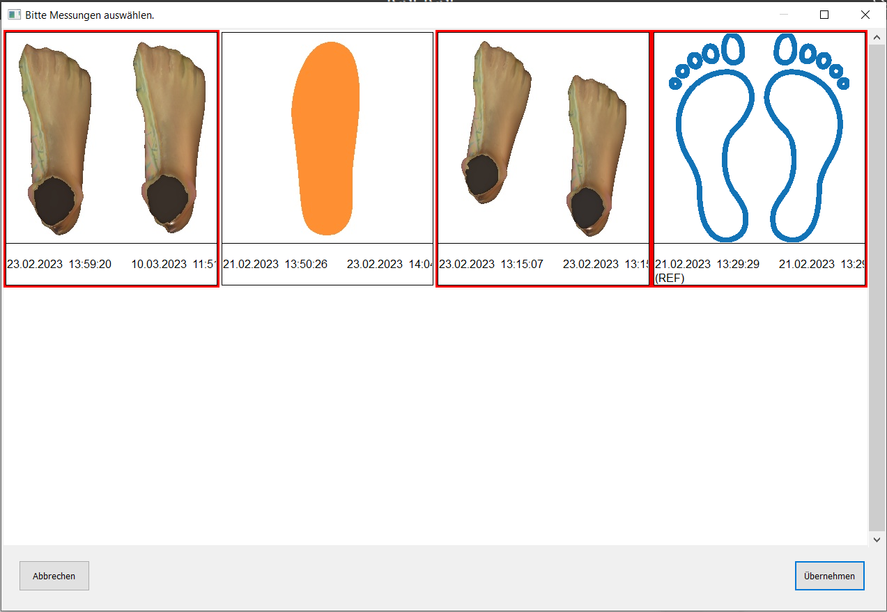
To select several at the same time, press the CTRL key and then select further measurements or constructions by clicking with the mouse.

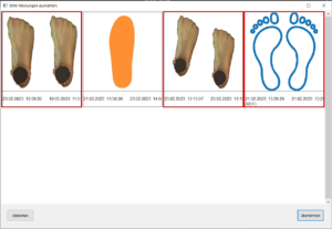
This is again indicated by the red border. Confirm this by clicking on the "Apply" button.

Next, select the storage location in the new window and confirm with the "Save" button.
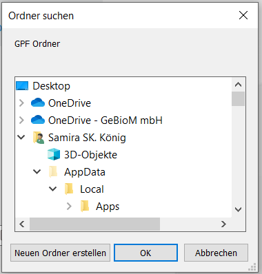
 

  1. Read folder


The "Read folder" tile is selected if a folder with several customers is to be integrated into the GP Manager.


Clicking on this opens a browser window in which the corresponding folder can be selected. This is done by clicking on the "OK" button.


  1. Save files as gpf


The "Save files as gpf" tile is selected if the complete data set or data from a specific date is to be saved or transferred.


Firstly, you can choose between "from specific date" and "complete" from the small tiles. If the tile is activated, it is displayed in a darker colour.


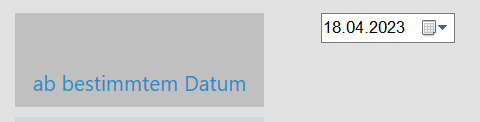
  1. as of a certain date


The "From a specific date" tile is selected to save or transfer data from a specific date up to today.

To do this, select the desired date in the drop-down menu next to the tile and then click on the "Save files as gpf" tile and select the storage location in the window that opens and confirm with the "OK" button.


Note: If today's data is to be backed up or transferred, a day before today's must be selected in the drop-down menu.


Once the process is complete, "Written files:... " appears in blue at the bottom centre.


  1. Complete


The "Complete" tile is selected to save or transfer the entire data record.


If this is activated, the "Save files as gpf" tile is clicked and the storage location is selected in the window that opens and confirmed with the "OK" button.


Once the process is complete, "Written files:... " appears in blue at the bottom centre.


Error description

During pressure measurement with MultiSens, individual columns or rows are grey throughout. Or the entire pressure measurement is red.

Cause of error

This fault is a defect in the pressure measuring plate.

Troubleshooting

Contact our support as the device needs to be repaired by us.

Error description

The GP M101 milling machine starts, but the spindle does not rotate during travel.

Causes of errors

A fine-wire fuse of the milling machine is often defective, please refer to the following document for the position of the fuses: "Fuses.pdf".

Troubleshooting

First look at the microfuse with the number 9, as this is the most frequently defective. However, also check the other miniature fuses. If none of the fuses are defective, please contact our support team.

Error description

The tiller does not start. Pressing the power button on the tiller has no effect. This error can occur with the following milling machines:

  • GP M101
  • GP M102
  • GP M103
  • GP M151
  • GP M302
  • GP M303
  • GP M251
  • GP M202

Under "View" -> "Status of the machine" boxes at the top right are highlighted in light red. This means that the limit switch has been triggered for this axis. In the example illustration, the negative limit switch of the X-axis has been triggered.

Maschinenstatus-2

Causes of errors

The router is in the limit switch position. This can happen if errors occur during milling.

Troubleshooting

The tiller must first be moved out of the limit switch position. This can be done in several ways.

  1. Start CNC Remote

 Option 1: Automatic release from the hardware limit switch:

  1. Click on "Control system
  2. Select "Options
  3. Click on "Release hardware limit switch"HW-endschalterfreifahren
  4. Follow the points below under "Reset the milling machine

Option 2: Release via manual control from the hardware limit switch:

  1. Select the hand symbol and then click on the green arrow pointing to the left.HW-endschalterfreifahren-2
  2. Follow the points under "Reset the milling machine

Option 3: manually release from the hardware limit switch:

  1. With our small milling cutters (not GP M303, GP M400, GP M400xxl), you can also move the milling cutter out of the limit switch manually.
  2. Open the door
  3. Move once slowly all axles by a few centimetres.
  4. Close the door
  5. Press the power switch.
  6. Press the reset button on the CNC Remote 1-2 times.Reset-button
    It should display the message "A reference run is required. Would you like to perform the reference run now?" appear. Confirm with "Yes„.

Reset the milling machine

  1. A dialogue should appear with the message "Power up servo amplifiers" dialogue box appears. Confirm this dialogue not.
  2. If the dialogue "Power up servo amplifiers" not:
    1. Check the status of the milling machine. Select "View" -> "Status of the machineMaschinenstatus
    2. In the following dialogue, the boxes at the top right should not all be greyed out. If this is the case, please contact support.
  3. First press the power switch.
  4. Now confirm the dialogue "Power up servo amplifiers" with "OK„.
  5. Press the reset button on the CNC Remote 1-2 times.Reset-button
    It should display the message "A reference run is required. Would you like to perform the reference run now?" appear. Confirm with "Yes„.Ref-Fahrt