Identify milling type with the GP Manager
The easiest way to recognise the type of tiller is in the GP Manager. To do this, proceed as follows.
- Start the GP Manager.
- Select "Analysis" -> "GP milling machine„.

- You can read the type of milling machine you are using in the GP milling machine module.

Identify milling type by appearance
There are several router series, which differ at first glance in the colour of the housing.
turquoise: 100 series milling machines (GP M101, GP M102, GP M103)
blue: 200 and 400 series milling machines (GP M201, GP M202, as well as GP M401 and GP M401xxl)
grey: 300 series milling machines (GP M301, GP M302, GP M303)
red: milling machines of the 50 series (GP M151, GP M251)
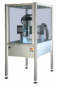
100 series

All 100 series milling machines have a turquoise-coloured housing and are connected to an external computer via the COM port.
GP M101
These milling machines have a motor from Kress or Suna, the carbon brushes of these motors must be cleaned regularly. The computer is not integrated into the router and is connected with a COM cable.
GP M102/GP M103
Both milling machines have ISA750 motors, which are maintenance-free. The computer is integrated into the router. The GP M103 can be distinguished by the fact that it has two USB sockets and a switch at the bottom left (see picture below).

200 series
All milling machines in the 200 series have a blue housing.
GP M201
300 series
All 300 series milling machines have a grey housing. All milling machines are controlled via a COM port.
GP M301
The GP M301 is controlled using the GP Remote programme and connected to an external computer via a COM cable.
GP M302/GP M303
On both types of milling machine, the type plate is located at the bottom left of the milling machine (see picture below). The computer is integrated into the milling machine.

400 series
All 400 series routers have a blue housing. The difference between the GP M401 and the GP M401xxl is the size of the milling table.
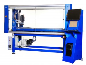
GP M401
The milling table of the GP M401 is 1205 mm long.
GP M401xxl
The milling table of the GP M401xxl is 1600 mm long.
50 series
All 50 series routers have a red housing and the computer is integrated into the router. The easiest way to distinguish between the two routers is by the arrangement of the buttons on the front.
GP M151
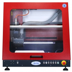
GP M251