Windows 8 does not allow unsigned drivers to be installed without further ado. To install an unsigned driver, you must start Windows with the driver signature deactivated.

  1. Move the mouse to the bottom right-hand corner. Click on "Settings" in the charmCham-Einstellungen-markiert
  2. Click on Switch on/off in the settings charm.Charm-Einstellungen-ein-aus-markiert
  3. Click on "Restart" while pressing the shift key
  4. In the following menu, select "Troubleshooting" -> "Advanced options" -> "Startup settings" -> "Restart"
  5. The computer will now restart, a selection menu will appear during startup, press button 7 to select "Deactivate driver signature".
  6. The computer now starts with the driver signature deactivated. This means that unsigned drivers can be installed until the next restart.


If the scan of a footfall foam leads to a poor result, the following reasons could play a role:

  1. The impact foam is simply too bad
  2. The tread foam is blue

Solution:

  1. Please make a new step foam or try to make the existing one usable.
  2. Please use a pink step foam (these are easily recognised)Blauer_Trittschaum

Instructions for milling blanks

There are several options available.

1. you can use a 3mm thick sheet of solid plastic (e.g. Plexiglas) for the suction table size and place on the suction table (the rubber mat still remains underneath). To determine the exact blank position, a special milling file is required (EF_Adjust_blank.CADF) which in the folder for the milling jobs (normally: C:\GeBioM_SQL\GpData\GpFraese\Inlays) must be copied. Now the special script must be added to the milling ini (normally: C:\GeBioM_SQL\GpSystem\Fraese\GPM_102.ini, GPM_202.ini or GPM_302.ini) (the GP Manager should of course be closed).

[Scripts]
T_Script_1 = ellipse_normal
T_Script_2 = ellipse_fine
….
T_Script_9 = rohling_grob
T_Script_10 = rohling_justieren (pay attention to the correct numbering!)

The EF_Rohling_justieren.CADF file is then milled on the plastic plate using the rohling_justieren script. Now you have the exact centre position of the blank. You can then adjust your Glue the blanks onto the plastic plate and instead of of the rubber mat into the table.

2. you can also use a mat that is at least 3 mm thick, e.g. made of rubber or EVA. This is also milled as described above. However, the outline of the blank is then milled onto the rubber mat. transferred and cut out (make sure to cut out the outline as accurately as possible, otherwise it may result in Vacuum loss can lead to). The mat is then placed on the existing rubber mat and the blanks are placed in The blanks are placed in the cut-outs, making sure that they are firmly sucked in. A separate mat is required for each type and size of blank. If you use this variant, you may only use the following scripts: rohling_normal, rohling_fine or rohling_coarse

3. make sure when designing that the specified centre line is not really centred on most blanks. The blanks are usually wider on the outside. This must be taken into account when positioning the inlay in the design programme, otherwise the inlay may not be milled exactly on the blank. All necessary files are also available for download at www.gebiom.de. If you have any further questions, please do not hesitate to contact us.

Your GeBioM / go-tec team

Files for download: blanks_milling Instructions_Fraesung_of_blanks


1. mark the position of the table with a fine pen
2. remove the cable tie from the tube
3. remove the 4 screws from the table
4. remove the tube from the table (like a screw)
5. remove the table and replace the new
6. replace the tube to table (like a screw)
7. place the table at the marks
8. fasten the 4 screws
9. replace a new cable tie to fix the tube
10. now you are ready to mill
Manual_Change_Vacuumtable

1. mark the position of the table with a thin pencil
2. remove the cable tie from the hose
3. remove the 4 screws from the table
4. remove the hose from the table (turn)
5. replace the defective table with the new one
6. reconnect the hose to the new table
7. align the table with the markings
8. tighten the screws again
9. secure the hose again with a cable tie
10. now you can mill again
Anleitung_Vacuumtisch_wechseln

Error description

It is not possible to create a 2D scan with the GP Manager, as after clicking on Scan page/Scan both the scanning process does not start.

Or the scanned image is not displayed correctly (black/white), or the foot outline is no longer recognised.

Causes of errors

The error can occur for various reasons. Examples of why this error occurs are

  • Windows cannot wake the scanner from sleep mode, therefore the scanner is not recognised by Windows
  • A file required by the driver is damaged or the driver is not installed.
  • The scanner is not properly connected to the computer or the power supply.
  • The settings for the scanner have not been selected correctly.
  • An incorrect power supply unit is being used for the scanner.

Troubleshooting

  1. Make sure that the scanner is connected to the computerand the cable is not damaged.
  2. Check whether the power supply unit belongs to the scanner. Make sure that the power supply unit is correctly connected to the scanner
  3. Is the scanner connected correctly:
    • Switch off the scanner (if possible) on the device. If this is not possible, unplug the power supply unit.
    • Unplug the USB cable from the computer.
    • Switch the scanner back on/plug the power supply unit back in
    • Plug the USB cable back into the computer.
  4. Start the GP Manager, select a customer and then the GP foot measurement module.
  5. Make sure that FootScan (for feet) or StepScan (for footprints) is selected.
  6. Check whether the scanner is working. Select "Scan both" and wait at least 30 seconds to see if the scanner scans an image.
  7. If an image has been scanned but the GP Manager does not recognise the border or the image does not look as expected, read on:
  8. In some cases, Windows changes the name of the scanner. If the scanner is stored with the name in the GP Manager and the display of the selection boxes is deactivated, the scanner is no longer displayed. In this case, follow the instructions in the IT manual for setting up a single workstation (Set up 2D scanneror contact the GeBioM mbH support.

General advice

To avoid mistakes in the future, the following procedures can help:

Error description

Logos other than the GeBioM logo should appear in the GP Manager. The GeBioM logos appear in the project overview, which is displayed directly after starting the GP Manager. And on the printouts, which can also be edited using the GP print page editor. If you do not want to change the print templates because you like the output of your printer, you can replace the logos directly.

GEBIOM11

Troubleshooting version 6

There are GeBioM mbH logos in several places in the GP Manager. If you want to replace these with your own logos, you can find and exchange logos as follows.

Firstly, you need to find the folder in which the GP Manager saves the logos.

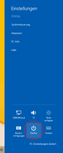
  1. How to find your GP Manager installation
  2. The folder contains the subfolder GpSystem\BMP. This folder contains the corresponding logos as BMP files
    1. Starter.bmp - Is displayed while the GP Manager is being started
    2. GEBIOM11.bmp - Displayed in the project view.
    3. GEBIOM12.bmp - Used for print templates.

    You can replace the corresponding logos with your own bitmaps.

Attention:
You must use bitmap files. It is not possible to use JPG or PNG files. If your logos have a different file type, open them in an image editing programme and save them as a bitmap.

The file extension is hidden in the standard Windows settings. You can recognise this by the fact that the GpSystem\BMP folder the files as Starter, GEBIOM11 and GEBIOM12 (without .bmp) are displayed. If you then add the file extension, the file in Windows is called Starter.bmp.bmp and is no longer found by the GP Manager.

Instead of the image, you will only see a red cross on a white background for incorrect files.

Troubleshooting version 7

To change the logo in the printout, please open the GP print page editor module. You will then find all possible GP Manager print pages under Templates. The default is GP_Print_Standard. If this page is selected, you can change the stored image by double-clicking on the current logo.

Version 7

Instructions for version 7 can be found in the GP Manager V7 manual

Version 6
Error description

A customer that has been created can no longer be found using the search functions in "Project" -> "Determine". It looks as if the GP Manager has deleted/lost the customer data or as if the customer was never created in the GP Manager.

Causes of errors
Several sources of error lead to this error. The GP Manager up to version 6.5 allows the entry of special characters and spaces in customer names. If these are at the beginning of the name, the customer can no longer be found; typing errors also mean that the customer can no longer be found.

Another possibility is that the first name and surname have been swapped during input. However, the GP Manager only searches for first names and customer numbers.

The GP Manager never deletes a customer once it has been created, so it only looks as if the user has disappeared. If a customer has been created, it is definitely saved.

Troubleshooting
Follow the path below to find your customer again.

  1. Start the GP Manager and click on "Project" -> "Determine" in the menu bar.GP-Manager-Projekt-offen-Bestimmen-markiert
  2. If you know the customer number with which the customer was saved, enter the Customer number in.Attention:
    Customer numbers always consist of two parts separated by an underscore "_". For the search to work using the customer number, you must enter at least the front part including the underscore. In the illustration under point 6, this would be "WS_"
  3. If you do not know the customer number, enter the following in the search mask Surnames of the customer.GP-Manager-Bestimme-Kunden-Suchfeld-markiert
  4. If you were unable to find the customer in this way, another possibility is that you have entered one or more spaces before the customer's name. Try searching for the name with leading spaces: " Surname"
  5. You may have mixed up the customer's first name and surname in the input mask. To be on the safe side, search for the First names of the customer.
  6. If you cannot find the customer in this way, another option is to search for customers who were created shortly before or shortly after this customer. For example, if you know the day on which you created the customer, you could search for other customers who had an appointment on that day. As an example, we have the customer "First name Last name", we can search for lost:
    Surname: Timelier
    First nameCustomer
    Customer numberWS_12
    search.
    GP-Manager-Bestimme-Kunden-Beispiel-Zeitnah-Kundennummer-markiertThe customer was created after our lost customer. This means that his customer number is larger. By searching for a customer number that is similar, we can try to find the customer again. For example, you can now search for "WS_11", "WS_13", etc.
    In our example, we find the lost customer via the customer number "WS_11".GP-Manager-Bestimme-Kunden-Beispiel-Vorherige-Kundennummer-makiert


Error description
When attempting to perform a pressure measurement, the following error messages appear in the GP Manager:

GP-Manager-COM-Port-nicht-gefundenCOM port not found: 6 For an automatic search, please switch off all other COM devices! If the COM port for the device is found, it will be entered in the CONFIG file! Should the COM port be searched for?
GP-Manager-COM-Port-nicht-gefunden-folgefehlerEven B_AUTO_COM did not help.
GP-Manager-COM-Port-nicht-gefunden-folgefehler2No connection to the measuring system found! Please check cables, power, configuration etc. ! No measurement can be carried out !

Causes of errors
The problem can have several causes:

  • The rechargeable batteries/batteries are no longer supplying sufficient power (a green LED does not mean that sufficient power is still being supplied). Therefore, first replace the batteries or charge the device before continuing.
  • The device is not or not correctly paired with the computer. In this case, the device must be reconnected to the computer (see below).
  • The Bluetooth stick is used on different computers or was previously used on a different computer (see below).
  • The radio connection is impaired or shielded by other devices (What needs to be considered for wireless connections?).

Troubleshooting

How you re-pair your device depends on whether you use the Bluetooth USB stick on one or more computers.

The Bluetooth stick is shared between several computers.

If you use your Bluetooth device on several computers, please follow the steps under "How to use your Bluetooth device on multiple computers„.

The Bluetooth stick is only used on one computer

If you only use your Bluetooth device on one computer, please follow the steps under "Re-establish lost Bluetooth connection„.

Error description

The milling machine is at a standstill, the CNC programme displays the error message "Only in simulation mode".CNC-Simulationsmodus-markiert

Causes of errors

The computer on which the CNC programme is installed cannot establish a network connection with the computer to which the milling machine is connected.

Troubleshooting

  1. Exit the CNC programme.
  2. Switch off the milling machine.
  3. Switch on the milling machine.
  4. Wait approx. 20 seconds.
  5. Restart the CNC programme.
  6. The milling machine should then work again as usual.