- The filament was empty before printing could be completed. Check whether the filament needs to be replaced.
- Printer firmware error. Check the printer screen for error messages. If the error message is not self-explanatory, contact support.
- During the printing process, there was something in the work area that was blocking the printer. Check the work area for foreign objects.
- The silicone sleeve of the print head has fallen off and is blocking the printer. Check that the red silicone sleeve is correctly attached to the print head. Make sure that the silicone sleeve is not cracked.
- The power supply to the printer was interrupted during the printing process. Check whether the printer is switched on.
- The print bed is too close to the print head during the first printed layer. Calibrate the height by following the print bed calibration (see Manual 3D printer Mike 2Chapter 8).
- The printer has run out of filament.
- The filament has become entangled in the filament chamber. Check the filament in the filament chamber.
- The filament is stuck in the print head. Use the filament change procedure (see Manual 3D printer Mike 2chapter 7) to remove the filament, cut off a piece of it and reinsert it.
- The print head is clogged and the print head needs to be cleaned. Carry out a cleaning process (see section 2).
- The printed part has a rough surface with small bubbles. This can happen if the filament is damp because the filament chamber is OFF or it has been stored in an uncontrolled environment.
- Check whether the filament chamber is connected.
- Replace the filament with a filament that has been stored in a dry and warm environment.
- Leave the wet filament in the (heated) filament chamber for at least one day without printing to dry it.
- The print surface is not clean. Wipe the print surface with isopropyl alcohol (see Manual 3D printer Mike 2Chapter 14).
- The print height is incorrect. Calibrate the height by following the print bed calibration (see Manual 3D printer Mike 2Chapter 8)
GeBioM/go-tec
M451
BZT (PFK 0403)
Set up/start:
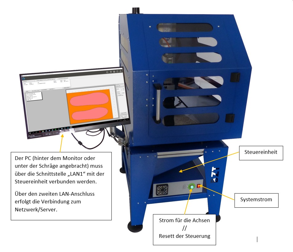
The PC, which is installed behind the monitor or under the slope, must be connected to the control unit via the "LAN1" interface.
The second LAN connection is used to connect to the network/server.
To commission the milling machine, please follow this procedure:
- Switch on the system power at the red toggle switch on the right.
- Start the PC and wait until the Windows system has fully booted.
- Switch on the power supply to the axles using the round, green pressure switch.
- Start the control software.
Software:
The CNC software requires real-time priority under Windows in order to control the machine correctly, which requires administrator rights. Ensure that the user logs in with a Windows profile that has administrator rights and that the software is started with the corresponding rights.
It is also recommended to deactivate the Windows User Account Control (UAC).
![]()
Errors in the control unit can be reset using the "RESET" button. It is also possible to reset the control unit using the green button on the control unit. To do this, the button must be held down for 2-3 seconds.
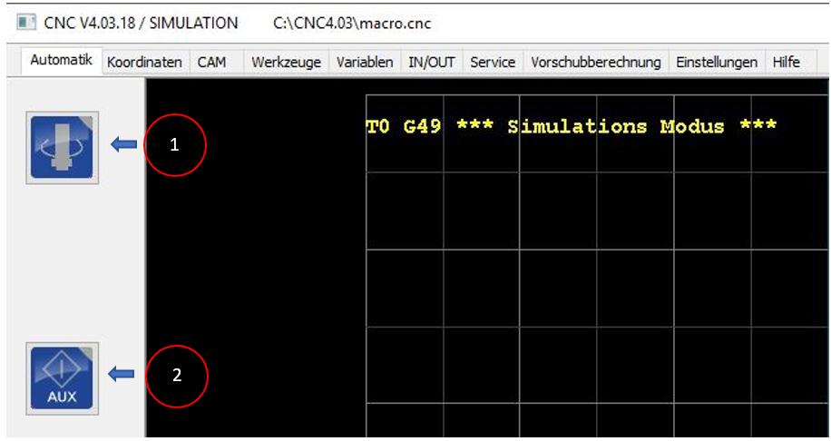
1: Manual switching on/off of the spindle motor
2: Manual on/off switching of the intake
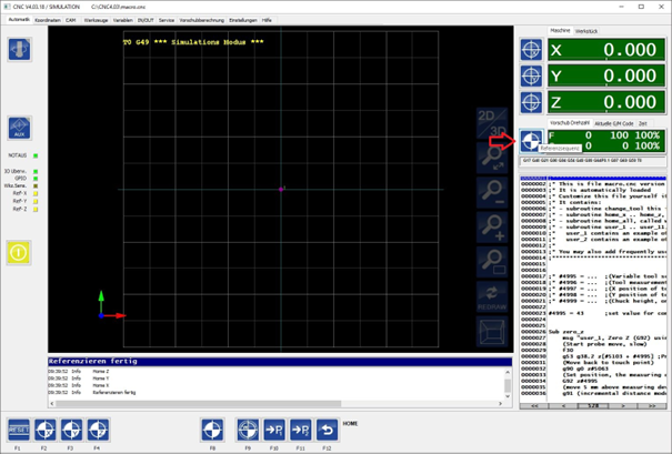
Referencing the axes:
![]()
Click on this button to open the menu for referencing the axes.
![]()
The corresponding axes can be referenced individually using the F2 (=x-axis), F3 (=y-axis) and F4 (=z-axis) buttons. The F8 button triggers a reference sequence for all three axes. The axes are then referenced one after the other in the order z, x, y.
The last button with the curved arrow takes you back to the home screen.
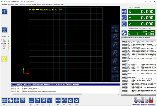
The reference sequence for all axes can also be started in the home view:
Start the milling process:
The F4 button takes you to the Auto menu.
![]()
The F2 "LOAD" button can be used to load the cnc file that is generated with the GP Manager. The default storage location is C:\Temp\Inlays.
The storage location is also displayed in the GP Manager:

Once the cnc file has been loaded, the milling process can be started with the F4 "START" button. The button then becomes the "STOP" button.
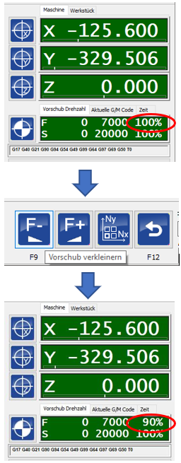
The F9 and F10 buttons influence the feed rate of the machine, i.e. the speed at which the axes are moved; per click +/- 5%. The value is displayed as a percentage in the main view below the position information:
Manual driving of the axles:
![]()
The F9 and F10 buttons ultimately have the same effect. With F9, the menu changes to the following view:
![]()
Pressing F10 opens an extra window with identical operating elements:
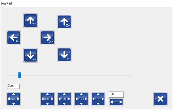
The axes can be moved using the arrow buttons. The buttons at the bottom are used to set the distance that the axes move with each click:
cont = The axle moves as long as the button/key is pressed.
0.001 - 1 = specification in mm
A freely selectable distance in mm can be entered in the last field.
The keyboard can also be used instead of the buttons:
Arrow keys right/left: x-axis
Arrow keys up/down: y-axis
Image up/image down (PgUp/PgDwn) = z-axis
Graphic:
![]()
The F8 button takes you to a menu which you can use to change the view of the graphic.
![]()
You can switch between 2D and 3D view or zoom in and out of the graphical view of the insert. The mouse scroll wheel can also be used for zooming.
The graphic can be moved in the window by holding down the left mouse button. If the Ctrl key is also pressed on the keyboard, the graphic can be freely rotated in the window.
Errors and troubleshooting:
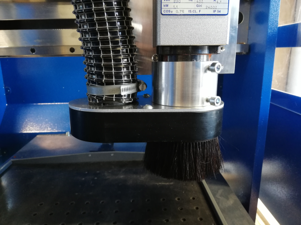
- The spindle no longer rotates on the M451.
It can happen that milling residue is deposited between the extraction bonnet and the spindle motor. As the spindle motor rotates, heat creates a ring of milling material that resembles a sealing ring and prevents the motor from rotating and ultimately blocks it.
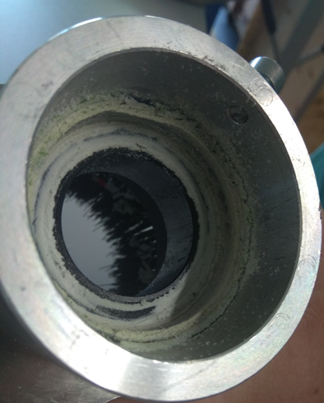
This ring can be easily removed by unscrewing the extraction bonnet and removing the ring of milling residue.
When refitting the extraction bonnet, make sure that the screws are not overtightened so that the spindle can rotate freely. Screws that are too tight can damage the spindle motor.
Machine (I/O menu)
![]()
The F7 "MACHINE" button takes you to the following menu
![]()
As in the main view, the suction and the spindle motor can be switched on and off here. In addition, the spindle rotation speed can be changed using the F9 and F10 buttons, each Click +/- 1%. The value is displayed as a percentage in the main view below the position information:

Installation/uninstallation of the CNC software from BZT:
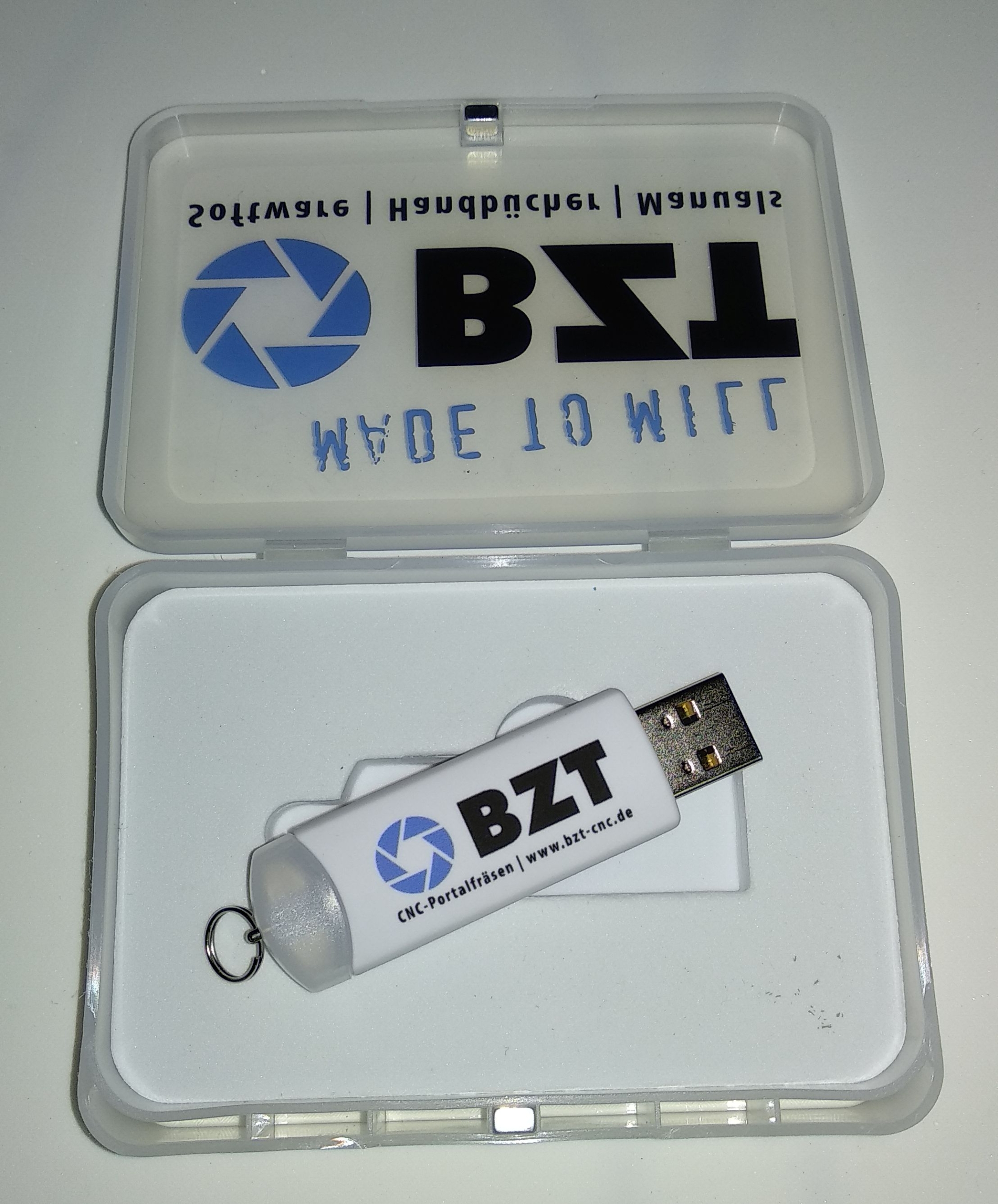
- Installation from USB stick via Setup.exe
- IMPORTANT: After installation, start the software before the parameters are copied!
- Exit the programme!
- Now copy the parameters manually into the root directory of the software. BZT does not recommend using the bat file for copying.
- To uninstall, exit the programme and run unins000.exe in the root directory. BZT advises against uninstalling the application via the control panel. Delete the programme folder manually after uninstalling.
The programme is supplied with the milling machine on a USB stick. The control software is customised for the specific milling machine. Please keep the stick safe and accessible. If there are any problems with the control software, the stick is essential for troubleshooting.
Simulation mode:
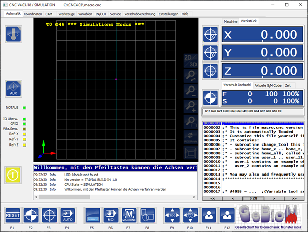
If the software goes into simulation mode after starting, it is very likely that the software was not terminated correctly, e.g. in the event of a system crash or by switching off the computer while the programme was still running. In these cases, incorrect configuration files can occur, which in turn means that the software only starts in simulation mode. The original files can be restored from the USB stick supplied. You will find them in the "Customer parameters" folder.
The software must be closed before restoring! We recommend creating a backup of the software in its current state before making any changes.
Copy the files from the Customer parameters folder on the USB stick to the root directory of the control software. The directory can usually be found on the drive C:\: C:\CNC4.03, or similar.
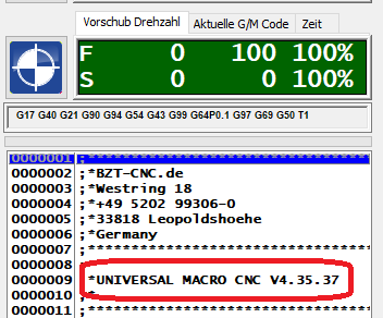
The machine should now restart in the correct mode. The correct software version will then also be displayed in the software:
Defective configuration files can be responsible for a variety of errors that manifest themselves in different reactions/unexpected behaviour of the machine, e.g. if one of the axes no longer stops during the reference run according to the display, but appears to move towards infinity.
Configuration of the network interface for communication with the control unit:
A network card must be assigned a fixed IP (IPV4) on the control computer:
IP: 172.22.2.150
Subnet: 255.255.255.0
Change milling cutter / determine zero point:
Remove the hose for material extraction. Then loosen the two screws on the extraction bonnet. The component consists of two parts: the extraction bonnet and the spacer ring. The spacer ring is attached to the spindle, the extraction bonnet to the spacer ring.
It is important here that both screws are not overtightened so as not to impair the free rotation of the spindle. Screws that are too tight can damage the spindle motor.
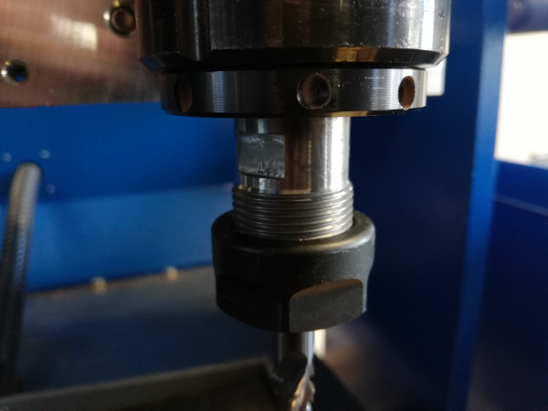
There are flattened points on the spindle shaft where a 20 mm open-end spanner can be used. A 30 mm spanner is supplied with the machine for the clamping nut.

After disassembly, please clean the clamping nut and collet from any milling residue.
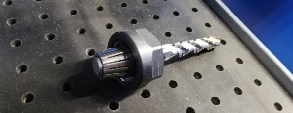
Snap the collet back into the clamping nut, insert the new milling cutter and reattach the clamping nut to the spindle hand-tight.
After changing the milling cutter, the zero point of the milling cutter must be redetermined!
To do this, move the spindle motor to the centre of the vacuum table using the "Manual movement" dialogue (see page 8). The rubber mat must be on the table. Use the arrows to move the
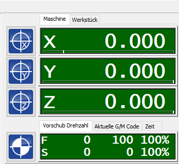
Move down the z-axis until the tip of the cutter almost touches the rubber mat. Now place a piece of paper under the cutter and move the z-axis further down until the tip scratches the paper but the paper can still be moved easily.
Make a note of the value that is displayed for Z in the coordinates. Make sure that the "Machine" tab is displayed, the coordinates are then highlighted in green. The coordinates in the "Workpiece" tab are highlighted in blue and must not be used!
Once you have determined the zero point, switch to the GP Manager. The value is entered in the GP InsoleFraese module. To do this, hold the Ctrl key on the keyboard and click on the "Set zero point" button.

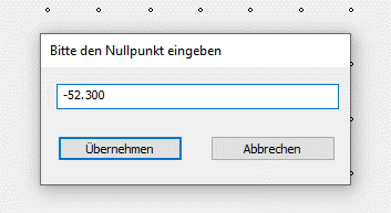
Click "Apply" to save the new zero point in the GPManager. Now create milling files with the new zero point. Old milling files that still exist must no longer be milled.
Basic information on changing collets:

You can also have your own insoles digitised and use them in your InsoleCad library:
- Please print the Declaration of consent from.
- fill them in completely
- Send us the signed Declaration of consent and your insole to be digitised in 3 sizes (size 35, 40, 45), or send us the measurements as described in the declaration of consent
- Address: GeBioM mbH
For the attention of Mr Petker
Wilhelm-Schickard-Str. 12
48149 Münster
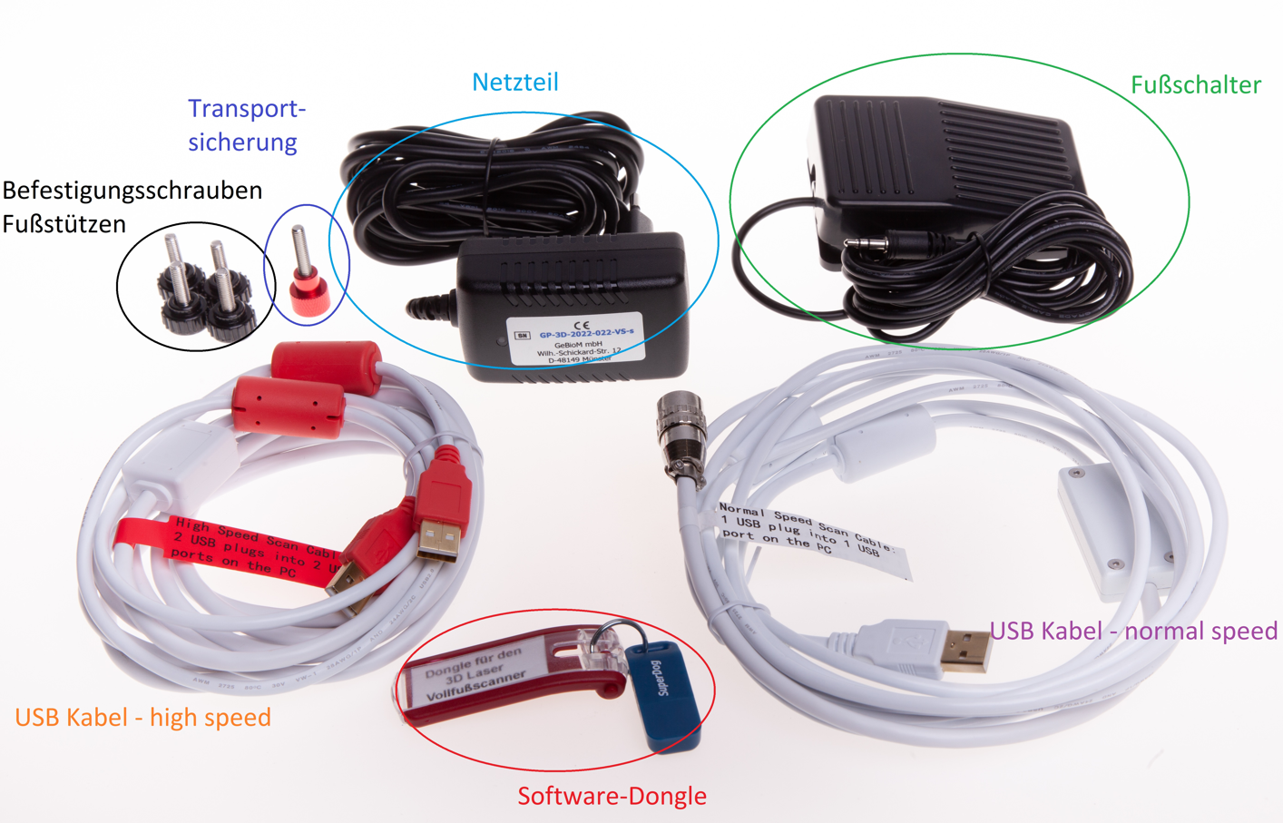
In addition to the scanner and the 2 side footrests, the following accessories are supplied:
There are various 3D full-foot scanners. The easiest way to differentiate between the scanners is by the housing.
- GT George
- GT George MAX
- GP LaserScan totalfoot one
If you need support, please also refer to our Compatibility list.
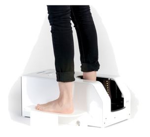
The full-foot scanner GT George is the current model.
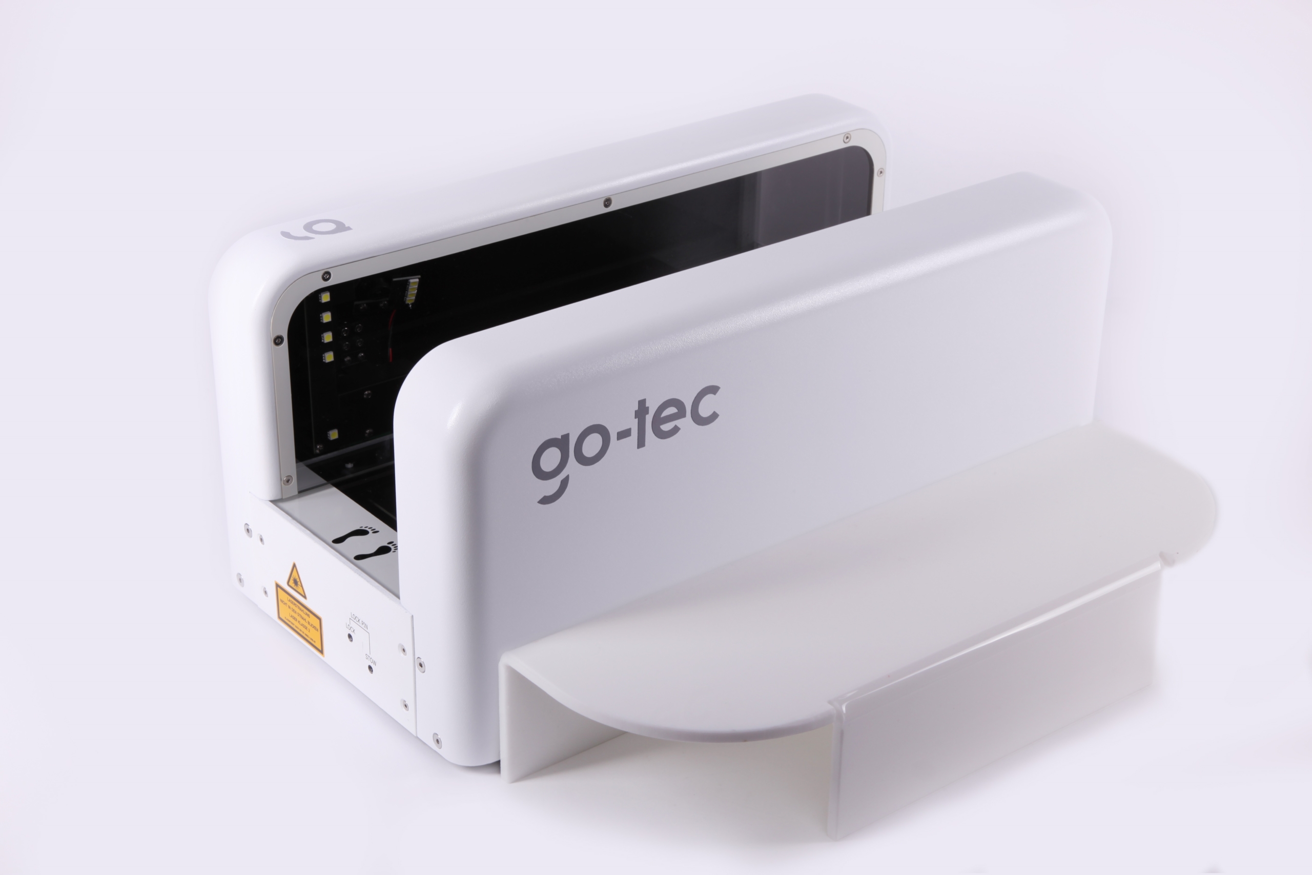
It is characterised by the fact that it only has two lateral camera guides and is open at the top.
The full-foot scanner GT George MAX is the "big brother" of the GT George and differs mainly in its higher scanning height of up to 17 cm.
The full-foot scanner GP LaserScan tf one is the predecessor model.
In addition to the lateral camera guides, the scanner is closed at the top by a cover.
The different models of the plantar 3D scanner you will find here.
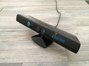
Two different 3D cameras can be used for the GP KinectScan / GP EasyScan 3D module:
- GP EasyScan / Kinect
- GP EasyScan-2 / Orbbec
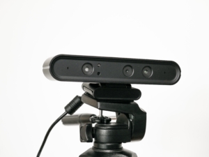


The main difference between the two cameras is that the Orbbec is only connected to your PC via USB, while the Kinect requires a power connection in addition to the USB connection.
When using the cameras, please always observe our Compatibility list.

With MultiShore materials, there is often a desire to align the insoles not to the rear edge (outer edge of the material), which is standard with block materials, but to a transition line between the materials. GP InsoleFraese offers the option of defining such materials.

This allows insoles of different sizes to be aligned at the transition line. This ensures that the desired material is always in the forefoot.
To do this, the material must be measured and a new placement must be specified in the INI of the milling machine (e.g. GPM_320.ini):
[Bestueckung_1]
T_Name = MS-BlackOrange // Can be freely named
T_Orientation = HOCHKANT // Alignment of the inlays on the table
T_Stop = LEFT BOTTOM // The material is created here
B_Use_Multi_Auftrag = yes // MultiAuftrag (yes/no)
I_Anzahl_Boxen = 0 // For small blocks it makes sense to define several boxes
B_MultiShore = yes // Use Multi-Shore
I3_MultiShore_Dimension = 345 285 30 // Fixed size of the material Length x width x height
I2_MultiShore_Transition = 185/245 // Change material FROM / TO (from material rear)
I_MultiShore_Nullline = 200 // Zero line for positioning the inserts
I_MultiShore_Nulllinie_Prozent = 100 // % specification of the rearfoot (from the heel) with which the insole is positioned
T_Arrange = COLUMN // Determine whether the LINE or the COLUMN is filled first