Problem:
You design an inlay and reduce the material thickness very much because you want to have a thin/flat inlay.
After milling, however, you now realise that the insert is larger than the insert you designed.

Cause of the problem:

The milling head cuts out a rim around the insert. This edge is as wide as the circumference of the milling head.
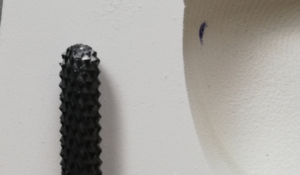
In the following pictures you can see the same inlay milled twice. Once with a material thickness of 1mm (start and end of the insert are marked with a blue line) and once with a material thickness of 10mm. The difference becomes clear here

Problem solution:

Do not cut out the inlay directly on the edge of the milling block, but on the inside of the milling head.

Control option:

Design the inlay once with a higher material thickness and mill out this inlay once as a test. If the inlay fits this time, then you have simply cut out the inlay a little too generously.

From version 7.3, the order of the individual discs in the GP shop can be changed.

Fixed are start page (window_1), customer page (window_2), print (window_14) and order (window_15). All other pages can be arranged individually in the following ini:

GP_TP_Branch.ini

[MODULE_WINDOW_FLOW]
MODULE_WINDOW_1 = BRANCH_HOME
MODULE_WINDOW_2 = BRANCH_ORDER
MODULE_WINDOW_3 = PHOTO_RECIPE
MODULE_WINDOW_4 = 3DSCAN_3DSCANF
MODULE_WINDOW_5 = PHOTO_VIDEO
MODULE_WINDOW_6 = DV_MULTISENS
MODULE_WINDOW_7 = DV_BALANCE
MODULE_WINDOW_8 = 2DSCAN_FUSSSCAN
MODULE_WINDOW_9 = 2DSCAN_TRITTSCAN
MODULE_WINDOW_10 = PHOTO_PHOTOS
MODULE_WINDOW_11 = INSERT_ARTICLE
MODULE_WINDOW_12 = INSOLE_SHOES
MODULE_WINDOW_13 = BRANCH_EXTRAS
MODULE_WINDOW_14 = PRINT_BRANCH
MODULE_WINDOW_15 = SEND_BRANCH

From version 7.3, you can set whether or not a printout must be made in the GP shop. The corresponding parameter can be found here:

GP_TP_Branch.ini

[Print]
B_Check_Print = yes // yes = it only continues after a printout, no = the next page is also reached without a printout

Summary:

  • With the F2 laser scanner, you can digitise footfall foams
  • you can then use the measurement in the GP InsoleCad module for the insole design
  • What is the optimum impact foam?
    • 4 cm deep, pink tread foam is used
    • it is advisable to work with cling film when taking the impression
    • Position the foot in the centre of the step foam
    • Partially or fully loaded
    • Press away unwanted undercuts with your finger on the tread foam
  • How do I make a good measurement?
    • When measuring, the heel of the step foam must point towards the go-tec logo
    • the impact foam must lie flat on the scanner
    • the inlet must be centred on the scan surface
    • Avoid unwanted finger impressions or similar in the tread foam, or tape over them

Summary:

  • With the F2 laser scanner, you can capture the plantar foot shape directly in 3 dimensions in the GP LaserScan module. You can also digitise impact foams.
  • The measurements can then be used in our CAD modules.
  • The measurements can be carried out partially or fully loaded
  • The following points must be observed:
    • Position the foot in the centre
    • Toes must point in the direction of the go-tec logo
    • Roll up your trousers
    • Take off your socks
    • The scanner window must not mist up
    • No other objects in the vicinity of the scanning area during the scanning process
  • Choice of location
    • Do not place directly next to the window
    • No direct lighting from above
    • No mirrors in the immediate vicinity


Problem description:

If you open the GP FootMess3D module and want to start the measurement process with the full foot scanner, the following message appears:

This means that either the dongle for the scanner is not connected to the PC or it is not recognised.


Solution:

Make sure that this dongle is connected to your PC via a USB port:

Under Control Panel -> All Control Panel Items -> Devices and Printers, the dongle should appear as "SuperDog".

If the dongle does not appear there, please plug it into another USB port.


Open the GP Admin module

and click on "Calibrate screen"

A window will now open in which you must select whether you want to align the square shown there to 10x10cm, 20x20cm or 30x30cm. Once you have decided on a size, drag the window in length and width so that the square (circled in blue) has these dimensions. Use a ruler, tape measure or folding rule held up to the screen. When the dimensions match, click on the [Apply calibration] button.

Close the GP Manager and restart it. Only then will the calibration be accepted.


Problem description:

If your computer has internal Bluetooth, problems may occur if you also want to use the Bluetooth dongle supplied. As a rule, the device manager will then indicate that there is a problem with the Bluetooth dongle and the pressure measuring plate cannot be connected to the computer.

Problem solution:

You can also connect your pressure measuring plate to the internal Bluetooth of your computer. You then do not need a dongle.
Follow the instructions when establishing the connection between the measuring plate and the computer: Re-establish lost Bluetooth connection

<iframe width=“560″ height=“315″ src=“https://www.youtube.com/embed/MWSWljmtCnE“ title=“YouTube video player“ frameborder=“0″ allow=“accelerometer; autoplay; clipboard-write; encrypted-media; gyroscope; picture-in-picture“ allowfullscreen></iframe>