How do I get a point to fit evenly on a moulding?
Error description
When a point is attached to a last, there is always a transition. This means that there is a clear transition between the old last and the new tip in the form of a kink, a dent or a bump.
Causes of errors
Modelling a new tip requires some experience, as there are a few mistakes to avoid.
- The tip was pulled out too far after attachment.
- The cut surfaces were not set correctly.
Troubleshooting
- Start the GP Manager and select a customer
- Select the OptiCAD module
- Create a new data sheet
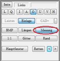
- Hold down the CTRL key and click on "Measurement„

- Choose a plaster scan
- Select 3D

- Select "<< Library tips" and select a tip

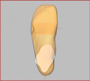
- In the main window, select "Transparent" so that you can see the measurement through the tip. The conical surfaces result from the incorrectly positioned cut edges.
- You can extend the tip by holding down the CTRL + left mouse button. Switch through the views to get an impression of the 3-dimensional shape.
- Only extend the tip so far that the transition is not visible as a large bump; this is only clearly visible in the inside and outside views.
- You can then adjust the length of the tip with SHIFT + left mouse button.
- The tip can be rotated in the views using CTRL + Shift + left mouse button.
- Conical surfaces during processing can be ignored; these surfaces come from the non-optimised cut surfaces.

- Switch to the front view, deactivate "Transparent„, „Draw CUT" and "Draw KANTE". This view gives you an impression of whether the tip may still need to be rotated (CTRL + Shift + left mouse button). The tip should cover the plaster in this view.

- Then activate "Draw CUT" and "Draw KANTE" again, leave "Transparent" deactivated.
- The next step is to model the cut edges. To do this, select "Cut surfaces" from.

- The light blue lines should run along the widest part of the moulding. You can move the lines by dragging the ends while holding down the left mouse button.
- Change the views to get a spatial impression
- Distribute the dark blue lines as evenly as possible.
- The green lines indicate the lower cut surface.
- If you have set the cut surfaces correctly, the conical distortions (point 8) should have largely disappeared (see illustration above).
