To define the degrees of hardness for your individual models on the insert, switch to the view from above [O]. With the right mouse button the individual models can then be selected (Figure 6).
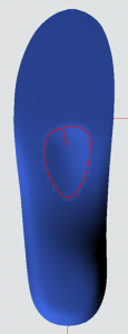
Figure 7 Selecting a model using the right mouse button

About the selection of Show body the degree of hardness for the model is adopted up to the bottom of the insert (Figure 7). If Show body not is selected, the degree of hardness is again only changed for the boxes that touch the top of the insole (Figure 8).

NOTE: Is Show body not is selected, it may be that the area for the respective degree of hardness is very low in height and therefore does not become soft during printing. We therefore recommend that you first define the hardness of the models over the entire height of the insole and then define the underside of the insole harder again afterwards. This ensures a soft upper side.

Figure 8 Pad selected as model -> Show body selected -> Degree of hardness is defined up to the bottom of the insole.

Figure 9 Pad selected as model -> Show body not selected -> Degree of hardness only defined for the boxes of the model that touch the top of the insole.

To make the transitions between hard and soft areas even smoother, you have the option of enlarging the models using the button [+1] and to reduce [-1]. This allows different transitions to be defined for the models. For models that are to be soft on the inlay, we recommend first enlarging the model twice and defining a degree of hardness of 35, for example. Then reduce the model using [-1] and define a hardness of 30. Then bring the model over [-1] to the original size and define a hardness of 20. This gives you a grading that takes place over a larger area (Figure 9). If this is not done, the degree of hardness is graded within a box. This procedure can be used to define the degree of hardness for each model accordingly. It can also be helpful to view the selected area from the side views [I] and [A] (e.g. Figure 7). This makes it easier to understand the effective range.

Figure 10 Degrees of hardness graded using the [+1] and [-1] buttons

It makes sense to first define a basic hardness for the insoles. To do this, select Show body and Show grid and select the desired degree of firmness for the insole. The colour of the boxes then changes.

Figure 6 Same degree of firmness over the entire insert.

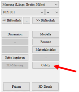
To select the extension, return to GP InsoleCAD. You will find the new Cubify button at the bottom right. Use this to open the hardness levels function.


The following view then opens.

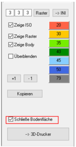
The user interface is structured as follows (Figure 2). In the top line, you have the option of setting the resolution of the grid used to create the PointCloud. We recommend a setting of 5 x 5x 5 mm. The standard setting for the grid can be saved in the INI using the à INI button. If your insert is not covered with grids over the entire top side, please click once on Grid. This regenerates the grid.

NOTE: The lower the resolution, the higher the computing power required for the design and the more time-consuming the creation of the print files.

Show ISO represents an isobaric representation of the degrees of hardness on the top of the insole.

Show grid represents the grid that is used for the PointCloud.

Show body defines whether the degree of hardness is defined over the entire height of the insert or not. Is Show body is selected, all boxes are selected (Figure 3). If Show body is not selected, only the boxes that touch the top of the insert are selected (Figure 4).


Figure 3 Show body selected -> All boxes of the insert are selected.

Figure 4 Show body not selected -> Only the boxes that touch the top of the insert are selected.

Fade displays the grids transparently so that the insert can be recognised. Will Fade is deselected, the underlying insert is no longer visible (Figure 5).

Figure 5 Fade not selected -> boxes are not transparent and the insert is not visible.

The different degrees of hardness can be selected on the right-hand side of the function box.

The button [CopyCopies the PointCloud to the other side.

NOTE: Only use if the left and right inserts have a similar structure. The entire PointCloud is copied and not aligned with the other insert. If you want to design different inserts, you must define left and right separately.

The button [3D printer] sends your design to the central production department at GeBioM mbH. Your inlays are printed there and then sent to you. The inlays are not sent to GeBioM by e-mail, but are stored securely in a cloud.

NOTE: The definition of the degrees of hardness is only saved when you return to the main window or when the deposit has been sent to GeBioM mbH.

Will Closing floor surface is selected, the underside of the insert is closed during printing (Figure 6).

To start GP GP InsoleCAD, you must first select a customer after starting the GP Manager. You can import customer data as usual via GP GPF.

To select a customer, click on    to search for the desired customer in the search field or create a new customer.
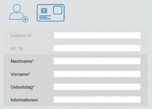
To do this, click on the customer symbol with the small (+) and fill in at least the fields marked with an asterisk.
Click on the back arrow  the customer is created for you and displayed in the GP Manager start menu.
You can also use the GP GPF module to import customer data from your database. To do this, first export the customer data from your respective GP Manager version via GP GPF and import this data into the soft database of your CUBIFY software via GP GPF.

NOTE: An error message appears when you open the GP GPF module. You can simply ignore this by clicking OK. You can then import your gpf files as usual.

You can then access the GP CUBIFY module via the GP CUBIX symbol.

As already mentioned, use an insole designed in GP InsoleCAD as the basis for the extension. This insole should have a flat insole designed in CAD+.

NOTE: If you want to specifically adjust the hardness levels for individual models on the inlay, these models must not be embedded in the inlay. If you want to cushion specific areas, it makes sense to position a model (e.g. lateral or MFK I lower) at this point and select a low height (at least 0.1 mm) for the model. This makes it easier to define the degree of hardness for this area.


The functionality and operation of the extension for the degrees of hardness in GP InsoleCAD is described below. Use an insole designed in GP InsoleCAD as the basis for the extension. This insole should have a flat insole designed in CAD+. For instructions on designing insoles in GP InsoleCAD and CAD+, please read the manuals under (https://gpsupport.de/handbuch-insole-cad/).


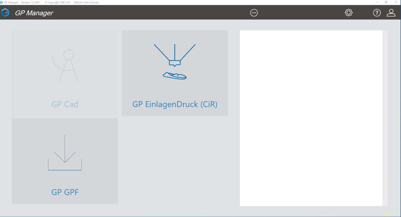
Start your GP Manager version. There is an additional GP Inlay Print module on the start page.


With the Cubify extension in GP InsoleCAD, you can design the upper side of your insoles as normal. You design the underside of the insole with CAD+ so that your insole fits the shoe perfectly. You can then use the GP InsoleCAD extension to determine the respective degree of hardness for each position on your insole to be printed. The extension is also characterised by the fact that the transitions between the degrees of hardness are graded, meaning that you do not have any hard transitions on the insole. This enables you to produce highly customised foot orthoses with precise relief, cushioning and support for your customers. Your designed insoles are then transferred to the 3D insole printing module. The print file (.gcode) for your insole is created in this module. We use the Create it Real online slicing API for this. This print file can then be printed with the GP Mike or GP Mike 2.


Any modern computer with a 3D graphics card has sufficient computing power to work with GP InsoleCAD and GP 3D InsolePrint. To create the print file, the computer must have access to the Internet. As GP InsoleCAD is part of the GP Manager, the system requirements are based on this. The following operating systems are supported:

  • Windows 10 (64 bit)

The following programme must also be installed Microsoft.NET Core Runtime 3.1.27 (x86). This can also be installed by the support employee