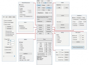
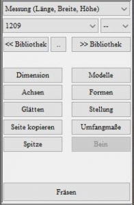
You can switch between different workspaces in the toolbox. If you change the workspace, the selection of tools available in the main window area changes. You can return to the standard workspace at any time by clicking on the [Main window] button in the function box.
The top menus in the toolbox are for using the moulding library. You can load mouldings in different sizes from your libraries and save your own mouldings in your library.
The toolbox is the area between the function box and the dimensions box. Depending on the selected workspace ("Dimensions", "Shapes", "Axes", "Models", etc.), various operating elements are displayed in this area. By clicking on the [Main window] button in the function box, you can switch back to the standard workspace at any time.
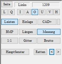
The various views and different display options can be selected using the function box.
With [L] [Q] you can view both bars side by side or on top of each other in landscape and portrait format. Press [I]- Inside, [A]- Outside, [O]- Top, [U]- Bottom, [V]- Front, [H]- Rear to switch views.
Click on the [Mouldings] button to activate or deactivate GP OptiCAD Click on the [Insert] button to activate or deactivate InsoleCAD. Click on the [CAD+] button to activate the CAD+ module, where you can create a gross moulding in GP OptiCAD.
If you have selected a measurement as the basis for the moulding, you can display the corresponding plantar image by clicking on [BMP]. Click on the [Lengths] button to display the dimensions of the moulding (length and width). With CTRL on the [Measurement] button you can select a measurement and with a single click on this button you can activate or deactivate the measurements. With a calibrated screen, you can display the moulding in its original size (scale 1:1) by clicking on the [1:1] button. Click on the [Grid] button to display the bar as a grid structure. Hold down the CTRL key and click on this button to place this structure on the moulding.
With GP CAD+ activated, you can create a gross bar by clicking on the [Gross] button and then holding down the CTRL key and clicking on the [<<Library] button.
Individual work steps can also be saved using [Save]. The [Main window] button always takes you back to the standard view of the toolbox.
The toolbar is located on the right-hand side of the screen and contains all the functions you need to edit the strips.
In the workspace, mouldings from the library or your own designed mouldings are displayed and edited.
Click on the "Page" button in the function box to change the bar to be edited (right/left).
The user interface of the CAD module consists of the menu bar (1), the workspace (2) and the toolbar (3).
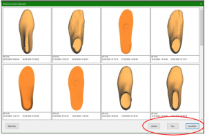
The menu bar displays the customer that is currently selected and being edited (1). The arrow (2) takes you back to the start page. The "Archive" button (3) can be used to load previous designs (by clicking on the [Select] button) and delete them (by clicking on the [Delete] button) or start a new project (by clicking on the [New] button).
The GP CAD module itself is divided into the workspace, where the 3D model to be modelled is displayed, and a toolbar on the right-hand side of the screen. The range of functions differs depending on which CAD modules you have purchased. You can see the activated modules in the function box (bars, insert, CAD+); if one of the buttons is not active, the module is deactivated. This is always the case if you have not purchased the module or if you do not need these CAD functions at the workstation.
The following section describes the basic organisation of GP OptiCAD. To start GP OptiCAD, you must first select a customer after starting the GP Manager.
To do this, click on to search for the desired customer in the search field or create a new customer.
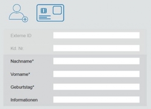
To do this, click on the customer symbol with the small (+) and fill in at least the fields marked with an asterisk. Click on the back arrow
the customer is created for you and displayed in the GP Manager start menu.
You can then access the GP CAD module via the GP Cad symbol.
GP OptiCAD (CAD = Computer Aided Design) is used to model mouldings and is part of the GP CAD module.
The GP CAD module consists of the GP OptiCAD module and the modules:
- GP InsoleCAD: The module enables the modelling of insoles.
- GP CAD+: Allows modelling of the underside of inserts.
The workstation at which you use GP OptiCAD is independent of where your measurement data is collected or where your milling machine or 3D printer is located. The required measurement data can be transferred to the GP OptiCAD computer via a network if required.
You can incorporate information about your customer's foot into the design using various measurement methods (3D and 2D scanning methods).
After construction, the finished lasts or trial shoes can be transferred to the milling machine or 3D printer, to another computer or to an external partner.
Five points are decisive for optimally designed mouldings:
- The measurement and its interpretation (3D scan, 2D scan)
- The moulding library and its adaptation to your wishes/handwriting
- The software, its editing options and usability
- Your ability to apply and implement positions 1-3
- The milling machine and its accuracy or the 3D printer and its accuracy
All elements have the same high priority.
Every modern computer with a 3D graphics card has sufficient computing power to work with GP OptiCAD. As GP OptiCAD is part of the GP Manager, the system requirements are based on this. The following operating systems are supported:
- Windows 7 (64 bit)
- Windows 8 (64 bit)
- Windows 10 (64 bit)