1. Plug the WLAN router (3) into a nearby socket. WLAN of the router corresponds to the serial number of the disc (GP-MS4-20xx-xx)
  2. Establish WLAN connection between router and PC (Password: 12345678)
  3. Switch on MultiSens platform (1)
  4. On the start page of the GP Manager, click the customer button Select and create new customer or search for existing customer
  5. With the arrow  Take over the customer and return to the start page
  6. Open GP foot pressure module
  7. The hardware GP MultiSens select
  8. Click on "Measurement" to start the measurement
 

  1. First walk over the platform with your left foot, then with your right foot
  2. The measurement is automatically saved and can then be analysed.
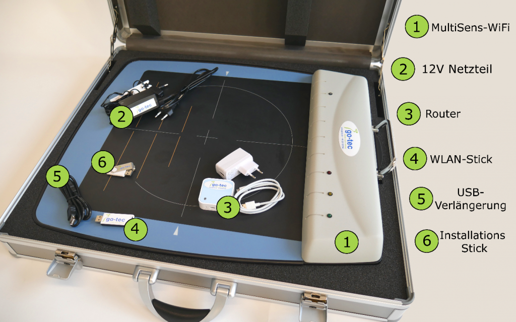
    Figure 21: Overview of scope of delivery

Measurements can be taken by clicking on the printer symbol  (top right) can be printed out. Various display options are available to you. If the basic or professional analysis is activated, the tables also appear on the printout.

You have the option of exporting the measurement you are currently viewing. The corresponding buttons can be found at the bottom right, or in older versions of the GP Manager under the cogwheel symbol.

The following export formats are available: Softcopy, DV Scan, JPG, PedCAD and ASCII. Select the desired file format from the drop-down menu and then click on "Export". Once you have selected the desired storage location, the corresponding file is exported.

Note: The entire customer is not exported. Use the "GP GPF" module for data backup or similar.

To import a PedCAD file, click on "Import" and select the desired file from the corresponding storage location.

A player function is inserted at the bottom right of the control panel.

This ensures that the dynamic measurement runs automatically. Click on the ">" play button to run the measurement automatically. When the measurement is running, a vertical line moves across the force-time curves at the bottom of the screen. Clicking the play button again stops the process and the vertical line remains at the corresponding position. As before, it is also possible to run the programme manually using the mouse or the cursor keys. By changing the percentage next to the player functions, it is possible to slow down the sequence from 30% to 100%. If the automatic sequence is paused, the measurement can be switched forwards and backwards in individual frames using the two arrow keys next to the play button.

When the comparison is activated (see 3.3.6 Comparison), the "Basic analysis" and "Professional analysis" boxes become active. These provide a comparison of the measurement data for the two measurements shown. After clicking on one of the two options, a table appears at the bottom of the screen in which various measurement data are compared with each other.

The basic analysis is divided into rearfoot and forefoot. The maximum pressure and impulse parameters are listed next to each other and the percentage deviations of the compared measurements are calculated.

Figure 19: Basic analysis

The professional analysis is divided into all foot zones (standard - 6 zones). The parameters Maximum pressure, Average pressure, Loaded area, Impulse, Force and Force rate are listed next to each other and the percentage deviations of the compared measurements are calculated. If the analysis is activated, the table also appears on the printout.

Figure 20: Profile analysis

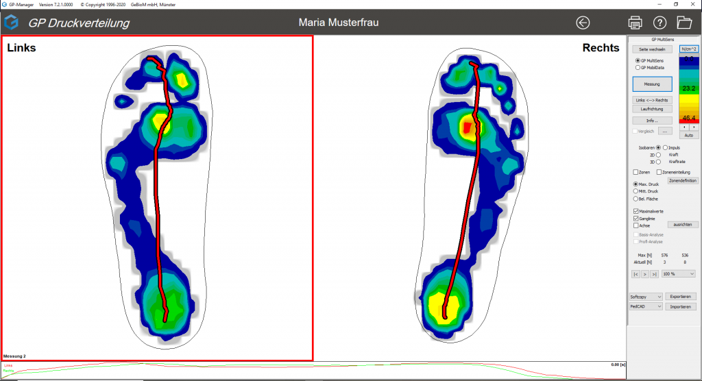
By activating the "Chart" checkbox, the chart is shown in the measurement display (red line). The pressure centre is calculated at every point during the measurement. This is marked as a point in the dynamic progression. The hydrograph represents the connection of the pressure centres of all individual images and is to be interpreted as the point of application of the body's centre of gravity.

Figure 18: Hydrograph

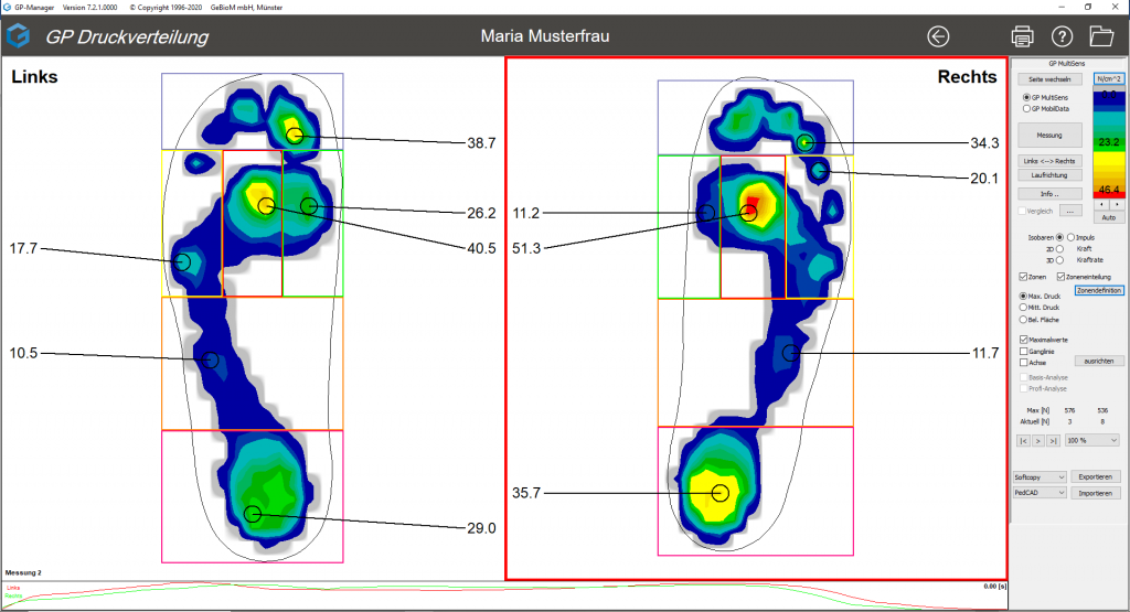
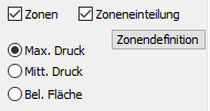
The "Maximum values" checkbox displays the maximum value for each foot zone (see Figure 14). This display is also active when an old measurement is called up.

If the feet are not displayed exactly vertically, the defined zones may not correspond exactly with the foot. The zones can be rotated by activating the tick next to "Axis", aligning the red axis with the foot and then clicking on "Align". 

Figure 14: View of the different zones and their maximum pressure values

It is possible to edit the zones manually. This function is only possible if "Axis" is not ticked. All changes made on one foot side are automatically transferred to the other foot side. Operation is carried out by holding down the Ctrl key. There are several options:

  1. Change an existing zone
    • click on the zone to be changed while holding down the Ctrl key and change the size of the zone at the corner or side points with the mouse, or change the position of the zone while holding down the mouse button in the zone

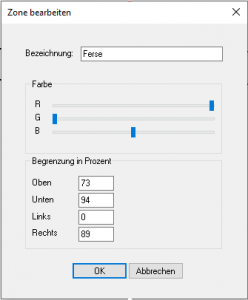
      Figure 15: Edit zone

    • double-click in the zone while holding down the Ctrl key to open a new window (see Figure 15). Here you can change the name, the colour by moving the sliders and the size and position of the zone by entering the coordinates, whereby the numbers indicate the position of the zone as a percentage (e.g.: Top-0, Bottom-100, Left-0 and Right-100 encloses the entire foot).
  2. Define a new zone
    • A window can be opened by holding down the Ctrl and Shift keys. This is then a new zone and can now be edited in the same way as under 1.) "Change existing zone".

If a change has been made under 1.) or 2.), the option "Save zones" appears (see Figure 16). The changed zone arrangement can be overwritten there or a new zone can be created.

Figure 16: Save zone

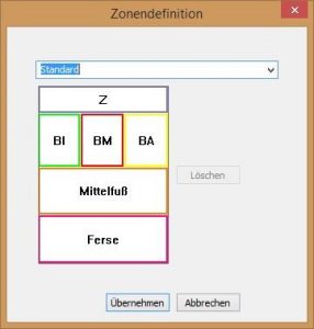
By clicking on "Zone definition", you can select from the list of zones that have already been created (see Figure 17). The selected zoning is displayed graphically and it is possible to delete a previously defined zoning.

Figure 17: Zone definition

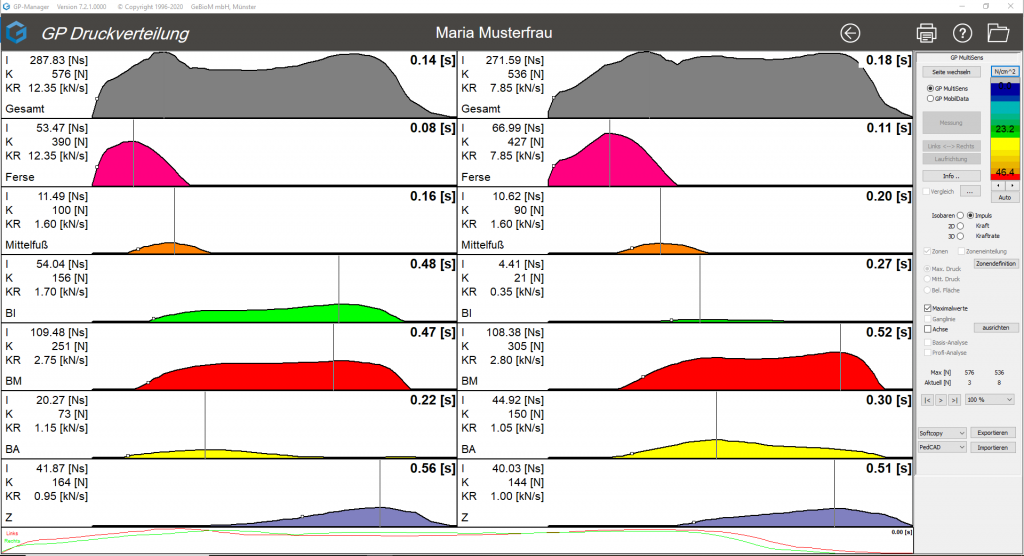
By activating the "Impulse, force, force rate" radio button, the force-time diagrams are displayed for all defined zones. The impulse, maximum force and force rate are also calculated for each zone.  

Figure 13: Illustration of impulse, force, force rate

These biomechanical parameters, which can be seen on the left of the curves, are helpful for a detailed gait analysis.

Parameters Abbreviation Unit Calculation Marking Biomechanical significance
Impulse I Newton*sec [Ns] Area under the curve (integral) coloured area Combination of height and duration of the load.

The greater the impulse, the higher and longer the load.

Maximum force K Newton

[N]

highest point of the curve vertical line Amount of load at an isolated point in time.

The higher the maximum force, the higher the short-term load.

Force rate KR Kilonewton per sec.

[kN/s]

Steepest ascent of the curve small, white square Speed at which the force is applied.

The higher the force rate, the weaker the cushioning at heel strike.