| Sequence |
Illustration |
Remark |
| 1. preparation: select the footprint; trace the outline with a black sharpie; place the footprint in the scanner |
|
|
| 2. start the GP Manager |
|
|
| 3. determining or creating a customer |
|
|
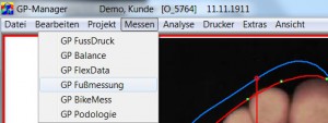
| 4. select foot measurement in the Measure menu |
 |
|
| 5. define the display range of the digitised image. Button: Left, Right |
 |
|
| 6. Select module if necessary - here: TrittScan |

|
|
7. button: Scan current view
The dialogue box can be switched off by the GP manager, in which case the scan is carried out with default values. If this is the case, continue with point 10. |
|
Call up the Twain dialogue box. This box can change from
others. |
8. Set parameters:
1) Colour resolution=colour
2) DPI : 100 |
|
in the Twain dialogue box |
| 9. scanning the template (footprint) |
|
in the Twain dialogue box |
| 10. If necessary, draw a rectangle in the digitised image to limit the right or left foot. |
|
Execution - if the foot outline was not recognised.
Drag a rectangle from the top left and bottom right while holding down the left mouse button |
| 11. button: Limit and 11. must be carried out separately for both zones of the working area |
 |
Deletes everything outside the rectangle |
| 12. Use the white-grey slider; click to the right or left of the red marker to adjust the threshold value for outline detection (to be carried out separately in both zones).
|
 |
Execution - if the foot outline was not recognised. |
| 13. Possibly correction of the longitudinal axis of the foot |
|
Move the mouse pointer to the toe point of the longitudinal axis (top), then hold down the left mouse button and move the mouse to the right or left. After reaching the correction point, release the buttons.Important: Waiting for the image to be recalculated |
| 14. Possibly correction of the outline |
|
Move the mouse pointer to one of the green dots, then hold down the CTRL key and press the left mouse button. Move the mouse pointer. After reaching the correction point, release the keys.Important: Waiting for the image to be recalculated |
| 15. setting the dimension lines (bale dimensions etc.) |
|
Move the mouse pointer to the end point of the line. Hold down the left mouse button and move the mouse. After reaching the correction point, release the buttons.
Important: Waiting for the image to be recalculated |
| 16. enter the manually measured circumference measurements in the measurement table |
|
|
| 17. button: Verticalise the foot axis |
|
Removes all parts of the image outside the outline and enlarges the image |
18th result bad New start by Button:
Calibrate; continue with 10. |
 |
New beginning |