Manual - GP CAD
1.Introduction
GP Cad is a module of the GP Manager. This module contains the sub-modules for inlay, bedding and slat construction. Double-click to open this module.
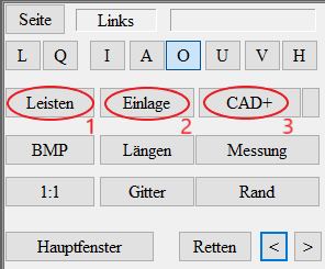
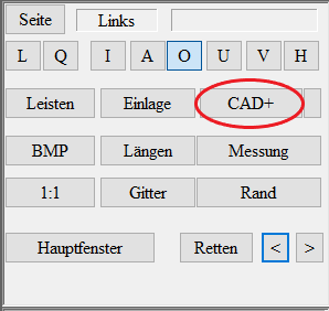
The GP Cad module contains the three sub-modules InsoleCad (2nd "Insoles" button), OptiCad (1st "Lasts" button) and CAD+ (3rd "CAD+" button). These sub-modules are purchased individually and activated accordingly by our support staff via remote access to your computer.
2.Overview of the submodules
Below you will find a brief overview of the sub-modules.
2.1.InsoleCAD
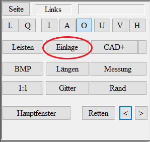
InsoleCAD is located behind the "Insoles" button.
This allows you to model the top of the inserts using 2D and 3D scans and pass them on to a 3D printer or milling machine to print/mill a finished insert. You can also define the share hardness for the 3D under the "Cubify" button.
A complete explanation of the InsoleCAD module can be found in the GP InsoleCAD manual.
2.2.OptiCAD
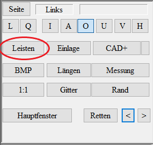
OptiCAD can be found under the "Strips" button.
This allows you to model lasts with the help of 2D and 3D scans and pass them on to a 3D printer or milling machine to print/mill a finished last. You can also create a trial shoe without first having a real last.
A complete explanation of the OptiCAD module can be found in the GP OptiCAD manual.
3.3D bedding
Firstly, the insert is selected from the library as usual and moved to the zero line using the "Dimension" button.
Now press the Ctrl key and the "Measurement" button to insert a 3D measurement into the view.
Click the 3D Subgrade button to access the 3D Subgrade module. The customisation options in the individual views Exterior/Interior view, Bottom/Top view, Front view and Rear view are explained below.
Exterior/interior view
Hold down the left mouse button and move the red dot at the height of the bale so that the measurement on the bale matches the insert. The second red dots at the front and rear can be used to adjust the measurement at the front and rear to the insert by holding down the left mouse button. The measurement is raised or lowered at the front or rear with the outermost red dot. The height of the red dot in the area of the longitudinal arch can be adjusted by holding down the left mouse button. If the "Ctrl" key is held down and the left mouse button is pressed simultaneously on the red dot in the longitudinal arch, it can be moved to the left and right and the centre of the longitudinal arch can also be adjusted.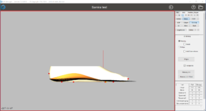
Lower/upper view
The centre red dot can be used to move the entire measurement by holding down the left mouse button. With the other two red dots, the measurement can be rotated around 2 different axes by holding down the left mouse button. The orange dots allow you to adjust the width of the measurement by holding down the left mouse button. The green dots, which are connected by a line, can be moved to define the transition between measurement and insertion in the bale area. The effects become visible when you activate the "Similar" option and use the "Emboss" button.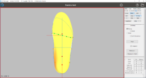
Front view
You can use the orange dots to incorporate the pronation or suppination position into the measurement by holding down the left mouse button.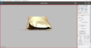
Rear view
You can use the orange dots to incorporate the inversion or eversion position into the measurement by holding down the left mouse button.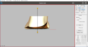
Setting options
If you select the Insert option, the measurement is hidden and a grid is displayed from below.
The option Adopt forefoot also imprints the forefoot in the selected insole so that the toes are recognisable.
The transparent option allows the measurement to be brought into the correct position from all sides.
ATTENTION: This option does not show where the insert and measurement intersect.
The "Measurement 1:1" button takes over the construction and takes you back to the main window.
The "Measurement 1:1 + border" button accepts the construction with a border (moulding) and takes you back to the main window.

