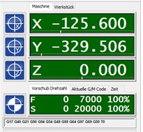
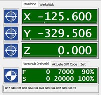
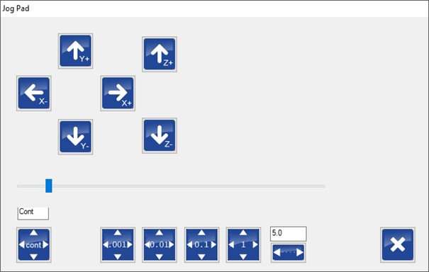
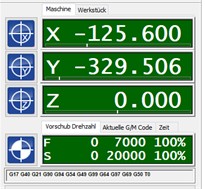
The laptop used to control the inlay milling machine only has 1 network connection. This is configured to a specific IP that must not be changed. IP V4: 172.22.2.120 The machine-side connection is located at the rear of the machine. The connection between the machine and computer is made via a normal network cable. To connect the laptop to the company's internal network, please use the USB C-to-LAN adapter supplied. The CNC software requires real-time priority under Windows in order to control the machine correctly, which requires administrator rights. Ensure that the user logs in with a Windows profile that has administrator rights and that the software is started with the corresponding rights. It is also recommended to deactivate the Windows User Account Control (UAC). The "RESET" button can be used to reset control unit errors. 1: Manual switching on/off of the spindle motor 2: Manual on/off switching of the intake Click on this button to open the menu for referencing the axes. The corresponding axes can be referenced individually using the F2 (=x-axis), F3 (=y-axis) and F4 (=z-axis) buttons. The F8 button triggers a reference sequence for all three axes. The axes are then referenced one after the other in the order z, x, y. Defined positions can be approached via P1 and P2. In the standard setup, these are P1 = home position and P2 = position for cutter change. The last button with the curved arrow takes you back to the home screen. The reference sequence for all axes can also be started in the home view: The F4 button takes you to the Auto menu. The F2 "LOAD" button can be used to load the cnc file that is generated with the GP Manager. The default storage location is C:\Temp\Inlays. The storage location is also displayed in the GP Manager: Once the cnc file has been loaded, the milling process can be started with the F4 "START" button. The button then becomes the "STOP" button. The F9 and F10 buttons influence the feed rate of the machine, i.e. the speed at which the axes are moved; per click +/- 5%. The value is displayed as a percentage in the main view below the position information: The F9 and F10 buttons ultimately have the same effect. With F9, the menu changes to the following view: Pressing F10 opens an extra window with identical operating elements: The axes can be moved using the arrow buttons. The buttons at the bottom are used to set the distance that the axes move with each click: The keyboard can also be used instead of the buttons: Arrow keys right/left: x-axis The F8 button takes you to a menu which you can use to change the view of the graphic. You can switch between 2D and 3D view or zoom in and out of the graphical view of the insert. The mouse scroll wheel can also be used for zooming. The graphic can be moved in the window by holding down the left mouse button. If the CTRL key is also pressed on the keyboard, the graphic can be freely rotated in the window. The F7 "MACHINE" button takes you to the following menu: As in the main view, the suction and the spindle motor can be switched on and off here. In addition, the spindle rotation speed can be changed using the F9 and F10 buttons, each Click +/- 1%. The value is displayed as a percentage in the main view below the position information: Installation/uninstallation of the CNC software from EDING Simulation mode: If the software goes into simulation mode after starting, it is very likely that the software was not terminated correctly, e.g. in the event of a system crash or by switching off the computer while the programme was still running. In these cases, incorrect configuration files can occur, which in turn means that the software only starts in simulation mode. The original files can be restored from the USB stick supplied. You will find them in the "Customer parameters" folder. Copy the files from the Customer parameters folder on the USB stick to the root directory of the control software. The directory can usually be found on the drive C:\: C:\CNC4.03, or similar. The machine should now restart in the correct mode. The correct software version will then also be displayed in the software: Defective configuration files can be responsible for a variety of errors that manifest themselves in different reactions/unexpected behaviour of the machine, e.g. if one of the axes no longer stops during the reference run according to the display, but appears to move towards infinity. Configuration of the network interface for communication with the control unit: A network adapter must be assigned a fixed IP (IPV4) on the control computer: IP: 172.22.2.120 Subnet: 255.255.255.0 All other protocols should be deactivated for this network adapter! After installing VPN software, it is possible that an additional protocol is active on the network adapters that prevents the connection to the control unit. These protocols must be subsequently deactivated! The network adapter on the control unit has the following IP: IP: 172.22.2.100 Subnet: 255.255.255.0 After changing the milling cutter, the zero point of the milling cutter must be redetermined! To do this, move the spindle motor to the centre of the vacuum table using the "Manual movement" dialogue (see page 8). The rubber mat must be on the table. Use the arrows to move the Make a note of the value that is displayed for Z in the coordinates. Make sure that the "Machine" tab is displayed, the coordinates are then highlighted in green. The coordinates in the "Workpiece" tab are highlighted in blue and must not be used! Once you have determined the zero point, switch to the GP Manager. The value is entered in the GP InsoleFraese module. To do this, hold down the CTRL key on the keyboard and click on the "Set zero point" button. Click "Apply" to save the new zero point in the GpManager. Now create milling files with the new zero point. Old milling files that still exist must no longer be milled! Assembly Dismantling Unscrew the clamping nut from the chuck. Press the collet chuck simultaneously in the two directions indicated by the arrows. Note Improper installation of collets can lead to damage to the collets and the clamping nuts, as well as to deteriorated concentricity. Avoid the use of force! Do not screw clamping nuts with incorrectly fitted collets onto your chucks. Always fit the collets to the clamping nuts first. Then screw the clamping nuts onto the chucks. Use the correct collet diameters! For example, if you want to clamp a tool with a diameter of 14.3 mm, please do not use collets with a diameter of 14-13 mm. In this case, please use collets with a diameter of 15-14 mm. To achieve the best possible result, insert your tool completely or at least 2/3 of its length into the collet. Incorrect insertion can lead to damage or a deterioration in concentricity. .
The manufacturer provides instructions on YouTube: Replacement carbon brushes can be obtained from go-tec. After three to four changes, it is advisable to have the spindle overhauled. In this case, you can send the spindle motor directly to go-tec. Manual - GT Rocky
1. scope of delivery
Subnet: 255.255.255.0 2. software
2.1 Basics


2.2 Spindle motor and vacuum

2.3 Referencing the axes


2.4 Starting the milling process


2.5 Feed rate


2.6 Manual movement of the axles


cont = The axle moves as long as the button/key is pressed.
0.001 - 1 = specification in mm
A freely selectable distance in mm can be entered in the last field.
Arrow keys up/down: y-axis
Image up/image down (PgUp/PgDwn) = z-axis 2.7 Graphical representation


2.8 Spindle


The software must be closed before restoring! We recommend creating a backup of the software in its current state before making any changes.
2.9 Setting the zero point
Move down the z-axis until the tip of the cutter almost touches the rubber mat. Now place a piece of paper under the cutter and move the z-axis further down until the tip scratches the paper but the paper can still be moved easily.


2.10 Basic information on changing the collet chuck
2.11 Changing the carbon brushes


