Insole CAD manual
1.Introduction
1.1.Installation
GP InsoleCAD is part of the GP Manager and must be activated by a GeBioM employee. If you GP InsoleCAD with the GP Manager, the module should already be activated.
Do you have GP InsoleCAD newly purchased, the module can be activated subsequently in a support session; the computer requires an Internet connection for this.
1.2.System requirements
Every modern computer with a 3D graphics card has enough computing power to work with GP InsoleCAD. Since GP InsoleCAD is part of the GP Manager, the system requirements are based on this. The following operating systems are supported:
- Windows 7 (64 bit)
- Windows 8 (64 bit)
- Windows 10 (64 bit)
1.3.What is GP InsoleCAD?
GP InsoleCAD (CAD = Computer Aided Design) is used for the modelling of insoles and is part of the GP CAD module.
The GP CAD module consists of the GP InsoleCAD Module from the modules:
- GP OptiCADThe module enables the modelling and milling of mouldings.
- GP CAD+: Allows modelling of the underside of insoles.
The workplace where you GP InsoleCAD It is not important where your measurement data is collected or where your milling machine is located. The required measurement data can be transmitted via a network to the GP InsoleCAD computer.
You can incorporate information about your customer's foot into the design using various measurement methods (various 3D and 2D scanning methods).
After the design, the finished insoles can be transferred to the milling machine, another computer or an external partner. The finished modelled insoles are manufactured using a CNC machine.
Five points are decisive for optimally designed insoles:
- The measurement and its interpretation (3D scan, 2D scan)
- The inlay library and its customisation to your wishes/handwriting
- The software and its processing options and usability
- Your ability to apply and implement positions 1-3
- The milling machine and its accuracy or the accuracy of the milling step calculation
All elements have the same high priority.
Familiarising yourself with a CAD programme is unfamiliar for any beginner. Complex 3D objects are displayed on a two-dimensional screen and can only be modelled there.
This way of working differs considerably from traditional craftsmanship. Experience in handling the new tools of the trade can only be gained through practical work with GP InsoleCAD.
2.Overview of GP InsoleCAD
The following section describes the basic organisation of GP InsoleCAD shown. To GP InsoleCAD you have to search for the start of the GP Manager first a Select customers. How to select a customer is explained in the GP Manager manual in section 4.7 Searching for/creating a customer.
You can then access the GP CAD module via the GP Cad symbol (Figure 1).
2.1.The GP CAD module
The GP Manager menu bar is located above the GP CAD module. Via the Arrow you can use the Exit GP CAD moduleYou will then return to the GP Manager start page.
The Question mark takes you to the GP Support Homepage (https://gpsupport.de). The computer requires an internet connection to load the page.
About the "Search/create customer" icon takes you to a view in which you can select a New CAD design or an already Existing CAD design can load/delete.
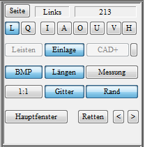
The GP CAD module itself is divided into the Work surfaceThe 3D model to be modelled is displayed here and a Toolbar on the right-hand side of the screen. The range of functions differs depending on which CAD modules you have purchased. You can see the activated modules in the function box (bars, insert, CAD+); if one of the buttons is not active, the module is deactivated. This should always be the case if you have not purchased the module or if you do not need these CAD functions at the workstation.
2.3.2.Toolbox
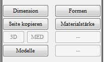
The toolbox is the area between the Function box and the Dimensions box. In this area, depending on the selected workspace ("Dimensions", "Moulds", "Material thickness", "Models"), various operating elements are displayed. By clicking on the "Main window" button in the function box can be used to switch back to the standard workspace at any time.
2.3.2.1.Library
The top menus in the toolbox are used to manage the insert library. You can use the menus to influence how existing insoles are loaded from the library. You can load insoles in different shoe sizes from your libraries and save your own insoles in your library. The exact functions are described in section 3.4.1 Library management.
2.3.2.2.Tools
You can switch between different workspaces in the toolbox. If you change the workspace, the selection of tools available in the main window area changes. You can return to the standard workspace at any time by clicking on the "Main window" in the Function box click.
3.Working with GP InsoleCAD
Now that you have an overview of the structure of the GP CAD module, the following sections describe the functions of GP InsoleCAD described in detail. As far as possible, an attempt is made to follow a practical workflow.
The GP Manager supports you in this, as the functions you need are arranged from top to bottom in the toolbar.
3.1.Create new deposits
To create new deposits for a customer, proceed as follows:
- Make sure that the button "Insert" is activated in the function box to enter the GP InsoleCAD module. If the button is active, it is highlighted in blue and "Insert" is displayed above the right-hand column in the dimensions box.
- Click on the "Search/create customer" icon. In the following dialogue at the bottom right, select "New".
- First select the "Page" (left/right insert) that you want to edit first.
- If you already have a measurement for the customer from another module, you can use Ctrl + left-click on "Measurement" to select a measurement. The individual measurements of the current customer are displayed in the following dialogue. You can select a measurement by double-clicking on it. You can also create an insert without a measurement if you do not have a measurement.
- Now select an insert from your library in the toolbox.
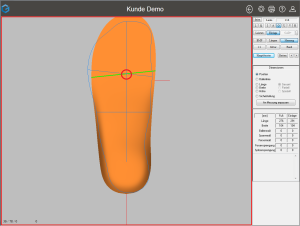
You should see a visualisation similar to Figure 9. The blue lines are the outline and bale line of the selected measurement.
If no blue line is displayed, then either no measurement has been selected or the inlay is covering the measurement. If you want to display the outline and the bale line of the measurement above the inlay, you can press Shift + left-click on "Measurement" change the view.
3.2.Functions of the work surface
The 3D model of the insert is displayed on the workspace. Using the buttons of the "Function box" (see sections 2.4 Function box and 3.3 Function box in detail), the display on the workspace can be customised.
To edit an insert, make sure that the button Insert is activated. If the button is activated, you are in the GP InsoleCAD Module. If you have already selected an insert, the insert is displayed on the workspace.
If you move the mouse cursor over the workspace, you will always see the current position in relation to the origin of the coordinate system at the bottom left. The origin is in GP InsoleCAD is always the point at which the bunion line intersects the foot axis.
Note: Remains the "Insert" button is greyed out after clicking it, the module is not activated. In this case, please contact GeBioM mbH Support.
Attention: If operation via keyboard shortcuts does not work, the GP Manager window is not active. Click once in the window to activate it.
3.2.1.Moving the insert
The insert can be moved on the work surface using the mouse or keyboard.
| Key combination | Mouse movement/button | Direction |
| Ctrl + left mouse button | forwards/backwards | Moving on the Y-axis |
| left/right | Moving on the X-axis | |
| any | Move along the mouse movement | |
| Ctrl + arrow key | top/bottom | Moving on the Y-axis |
| left/right | Moving on the X-axis |
3.2.2.Turning the insert
To view the insert from any perspective, you can rotate the insert using the mouse or the arrow keys.
You can rotate the model using the following key combinations:
| Key combination | Mouse movement/button | Rotation |
| Shift + left mouse button | forwards/backwards | Rotate around the X-axis |
| left/right | Rotate around the Y-axis | |
| Ctrl + Shift + left mouse button | left/right | Rotate around the Z-axis |
| Shift key + arrow key | top/bottom | Rotate around the X-axis |
| left/right | Rotate around the Y-axis | |
| Ctrl + Shift + left mouse button | left/right | Rotate around the Z-axis |
3.2.3.Zoom
The insert can be zoomed in to view details of the model.
| Key combination | Mouse movement/button | Zoom |
| Mouse scroll wheel | before | Zoom in |
| back | Zoom out | |
| < button | < | Zoom out |
| Shift + < key | > | Zoom in |
Note: When zooming with the mouse wheel, the perspective changes as the area under the mouse cursor is zoomed.
Attention: If zooming in with the mouse scroll wheel does not work, make sure that the window is activated. Click once on the workspace with the left mouse button. If the window is activated, make sure that the 1:1 view is not activated.
3.2.4.Trade fairs
To be able to measure, you must be in a standard view (see 3.3.3 Standard views). Move the mouse to the starting point from which you want to measure. Press the right mouse button and hold it down while moving the mouse.
The information on the measuring section is displayed in the bottom left-hand corner of the workspace.
- Current cursor position (relative to the origin of the coordinate system)
- Current cursor position (relative to the starting point of the measurement)
- Absolute length of the measured distance (in mm)
Note: If you want the most accurate measurement possible, zoom in as close as possible to the area to be measured. The smaller the insert is displayed, the greater your measurement error will be.
3.3.Function box in detail
Most of the buttons in the function box affect the display of the insert on the workspace. Some of the buttons can be activated by clicking on the button. These buttons are highlighted in colour when activated.
Clicking on the button again deactivates it. For example, by clicking on "Measurement" button to show or hide the currently selected measurement.
3.3.1.Page
With the button "Page" button to change the currently selected page (left/right). If a view of the workspace is selected in which the workspace is split (L/Q see 3.3.2 Views), the currently selected page is Red border.
The currently active page and the insole model from the library are displayed to the right of the button (if an insole model has been loaded).
3.3.2.Views
The workspace offers three different views for displaying the inserts (display of the current insert, both inserts next to each other, both inserts on top of each other).
The buttons "L" (lengthwise) and "Q" (crosswise) divide the work surface into two halves so that you can see the inserts for both sides at the same time.
If one of the two buttons is highlighted, click on it again to display only the currently selected insert.
3.3.3.Standard views
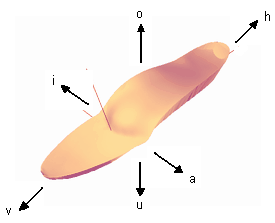
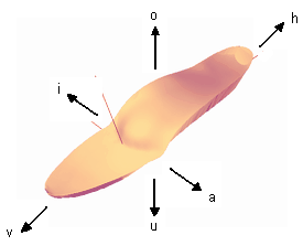
The following views are available as standard views (see Figure 11).
- I: Inside
- A: Exterior
- O: Top
- U: Bottom
- V: Front
- H: Rear
By clicking on one of these buttons, you can always display the insert in one of these views. If you position an insert manually on the workspace (rotate, rotate), you may leave the standard view. In this case, the button is also deactivated again.
Attention: If you want to carry out a measurement (see 3.2.4), a standard view must be activated (I, A, O, U, V or H).
If you want to display the current lengths (see 3.3.6 Lengths), you must be in one of the I, A, O or U views.
3.3.4.Insert
If you click on the "Insert" button, this has several effects. Deactivating the button hides the 3D model of the insert. At the same time, you leave the GP InsoleCAD module so that all functions of this module are deactivated.
All functions for selecting and editing inserts are no longer available. You will not be able to use these functions until you reactivate the button.
3.3.5.BMP
Via the button "BMP", the images of the foot read in from GP TrittScan, GP DvScan, GP FussScan, GP LaserScan or GP KinectScan, among others, are projected onto the insole. In order for an image to be displayed, it must first be activated with Ctrl + left-click on "Measurement" button to select a measurement and load an insert from the library.
3.3.6.Lengths
With the button "Lengths" the dimensioning of the insert is switched on or off. The following dimensions (in mm) are displayed for the dimensioning:
Overall length, forefoot length, rearfoot length, forefoot width, rearfoot width and toe allowance
Note: Please note that the lengths are only displayed in the standard views I, A, O or U.
The height is only displayed in views I and A, the forefoot and back foot width only in views O and U.
3.3.7.Measurement
With Ctrl + left-click on "Measurement" button, all measurements are displayed. A measurement can be selected to serve as the basis for the design.
With Shift + left-click on "Measurement" You can use for GP InsoleCAD Use measurements from the GP TrittScan, GP DvScan, GP FussScan or GP LaserScan 3D modules.
By clicking on the "Measurement" buttons to activate/deactivate it. If it is activated, the outline, the bale line and the foot axis are displayed in blue. For this to work, the lines must first be set correctly in the measurement module (GP TrittScan, GP DvScan, GP FussScan, GP LaserScan or GP KinectScan).
Note: If the contour line is missing or the bale line/foot axis is not set correctly, open the measurement in the measurement module again and set the lines.
3.3.8.1:1
Press the button "1:1", the insert is displayed 1:1. The prerequisite for this is correct screen calibration (see 4.1 How can I display an insert 1:1 ).
Attention: As long as the 1:1 display is active, you can no longer zoom in or out on the insert. To be able to do this again, you must first deactivate the 1:1 function.
3.3.9.Grille
With the button "Grille", the inlay is displayed as a grid. This provides a better impression of the 3D structure of the inlay.
3.3.10.Edge
If the Edge function is activated, not only the surface of the insert is displayed, but also the edge and the underside. This corresponds most closely to the finished milling result.
3.3.11.Main window
Via the button "Main window" button to return to the standard work area of the toolbox. All selected tools are automatically closed.
3.3.12.Rescue and < >
With the help of the "Rescue" buttons to save your current deposit at any time. Via the buttons "<" ">" button to switch between saved work steps.
Note: As in GP InsoleCAD If it is not possible to undo every single work step, it is advisable to create a backup with rescue before or after every major work step.
In general, you should get into the habit of using Retten frequently.
3.4.The toolbox in detail
Most of the functions of GP InsoleCAD are stored in the toolbox. To create an insert, you can work through the toolbox in the same order as you would read a book (see Figure 12).
3.4.1.1.Deposit calculation
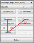
The top drop-down menu provides a selection of how the insert is adapted to the selected measurement. GP InsoleCAD offers several options for how this is calculated. By default, the two options Measurement (length, width, height) and Original size are activated. These two methods are sufficient for most cases. The other methods can also be activated on request.
Measurement (length, width, height)
- The inlay is adapted to the measurement in width and length. The corresponding height is taken from the grading table.
Original size
- The model of the insert is loaded from the library in the size in which it was saved there.
Note: Which options are available in the drop-down menu depends on the settings of the GP Manager installation. The following additional options are possible and can be activated on request. As a rule, however, these are not required.
Best possible size (stitch)
- The insole is adapted to the measurement in width and height according to the grading table. The next larger "shoe size" is used for the length of the measurement (plus toe allowance).
Specified size GP FootMeasure
- Manual adjustment of the customer's actual size. To be set by the person scanning/measuring the customer. The measured values are stored in the GP FussMess module and can only be entered in GP InsoleCAD be utilised.
Measurement (length, ball, heel)
- Predefined points at which a fixed value of millimetres is added to the insert.
- (tip/end)
- (Bale inside/bale outside)
- (inside heel, outside heel)
The points are displayed in the GP FussMess module and can only be set in the GP InsoleCAD be utilised.
Adopt only the form
- Existing models (pads, bars, etc.) are retained, only the inlay is exchanged with the selected inlay from the library.
Measurement (length, width)
Subsequently changes the size of the insole and all models (length/width) without changing the height, i.e. if this option is not activated, changing the shoe size also grades the models.
3.4.1.2.Selection of an insert
You can use the drop-down menu on the left to select an insert directly. The function corresponds to the "<< Library" button, but the selection via this drop-down menu is often faster than the selection from the graphical display.
Note: You can also click on the drop-down menu and then use the scroll wheel to scroll through the insoles. The insoles are loaded directly and you get an impression of the shape and models of the insoles.
3.4.1.3.Selection of shoe size
You can select the shoe size in the drop-down menu on the right.
Note: You can also click on the drop-down menu and then select the size using the scroll wheel. The insole is recalculated directly so that you get an impression of the size ratio of the insole and the measurement.
3.4.1.4.<< Library (search for and load insert from model catalogue)
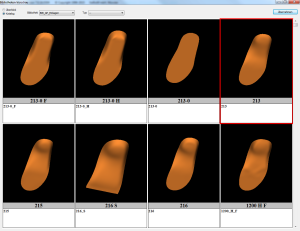
This button takes you to the model catalogue. Here you can display a preview of the insoles and load an insole.
The dialogue offers several options for adjusting the display so that you can find the insert you are looking for as quickly as possible.
Library
- Select the library in which you have saved the insert you are looking for.
Type
- Select the type/group of the insert you are looking for.
Note: Unfortunately, scrolling through the inserts only works properly using the buttons above and below the scroll bar. If you want to search through the insert library, it is best to use these.
Once you have found the insert you are looking for, mark the insert by clicking on it so that it is outlined in red (see figures Figure 15 and Figure 14). Then click on "Take over". Alternatively, double-click to load the insert immediately and close the dialogue.
If you do not wish to load an insert, close the dialogue window.
3.4.1.5.Library >> (Add insert to a library)
You can organise inserts in libraries. With every installation, you will find a selection of ready-made inserts in the library BIB_GP_Inserts. You can use these inserts as the basis for your own inserts. You must save the modified inserts in your own libraries. Of course, you can also create your own inserts from scratch.
Select "Library >>" to the "Add an insert to the library" dialogue.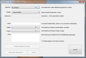
Library
Under Library, you can select the library in which you want to save the insert.
Note: Supplied inserts cannot be changed. If you want to change an insert, you must transfer these inserts to a customer library. To do this, load the insert, make any necessary adjustments to the insert and select "Library >>". Select a customer library and then save the insert as described below.
Library -> ...
With the button on the right (".."), you can rename libraries and create new libraries. You can also include and deactivate libraries (see ).
Models
You have the option of overwriting an existing model with the current insert. In this case, select the name of the model here. If you want to create a new insert, select "- New model -"
File name
The file name is derived from the model name. Nothing can be entered here. If you have selected an existing insert, the file name under which the insert can be found in the library folder is displayed here.
Name
Give the insert a name. The insert appears under this name in the model catalogue.
Attention: Do not use any special characters for the name. A file with the name of the insert is created. If the name contains special characters, the file cannot be created. Only use letters, numbers, spaces, hyphens and underscores.
Table
Enter a grading table for the inlay. This is used by the GP Manager to calculate the dimensions of the insert.
Table -> ...
With the button on the right ("..") you can enter the dimensions for the inlay manually or import an existing grading table. Please note that the numbers are written according to the English notation. A full stop is used here instead of a comma.
Using the number pi as an example, 3.14 becomes 3.14 in the English notation.
The measurements are given in the table in the following order: "Shoe size = length width height" (in mm).
Note: The GP Manager is able to calculate the grading table. To do this, you must enter the measurements for at least two shoe sizes. You will achieve the best results if you enter the measurements for shoe sizes 36 and 43.
Group
In addition to libraries, inserts can be organised in groups. You can select an existing group from the drop-down menu. In the model catalogue, you can display the inserts according to these groups.
Note: In the model catalogue, the groups are called "Type".
Group -> ...
With the button to the right of Group ("..") you can edit your groups. This makes it easier for you to find inserts in your libraries.
Note: If you have created a new group, it is displayed in the "Add an insert to the library" dialogue is only displayed after you have closed and reopened it once.
If you assign a number twice, it can happen that deposits are assigned to a group that already exists. You should therefore avoid assigning a number twice by mistake. It is advisable to leave larger number spaces between different groups. For example, you can start groups for adults only from 100. Groups for children's inserts from 200.
Info
The text entered here appears in the model catalogue under the respective insert.
Place the model as high up as possible
Select this option so that the insert is categorised at the top of the selection menu. You should select this for frequently used inserts. This allows you to find the inserts quickly in the main window.
Note: If you want to categorise existing inserts at the top, open the insert and select this option.
Insert model into library
This button is used to add the insert to the library.
Apply changes
This option writes the changes to the loaded insert. This means that the insert currently displayed on the workspace is saved with the changes. If you only want to rename existing inserts, you must ensure that the insert you want to rename has been loaded from the library beforehand.
Delete
The insert selected under Models is deleted from the library.
Back
You return to the GP InsoleCAD module without making any changes to the library.
3.5.3D modelling of insoles with GP InsoleCAD
The descriptions in this manual only refer to the modelling of the top side of inserts. If you are interested in modelling beddings, you must consult the CAD+ manual and have purchased the corresponding module.
All the functions required for 3D modelling are located behind the buttons in the toolbox. You can easily memorise the workflow by imagining you are reading a book. It is recommended to use the buttons in the same order.
The exact procedure depends on whether you start with a 3D measurement or a 2D scan (see Figure 12: Recommended work sequence).
There are generally three different options for modelling: Total, Partial and Especially. These always refer to the current context. If you are modelling the insert, the mode refers to the insert. If you are currently editing a model, this mode only applies to the model. Changes in the modes are always carried out with Ctrl + left mouse button + mouse movement.
Depending on the mode, the position of the mouse click determines which part is changed.
TotalTotal is the coarsest mode. If this is activated, the entire insert or the entire selected property such as length, width, etc. is changed. This mode allows you to roughly customise the insert. For example, if "Dimensions" -> "Width" is selected, the width is adjusted on both sides.
PartialPartial is the next finer mode. In this mode, part of the currently selected Wenur is changed. For example, if the "Dimensions" -> "Length" is selected, only the length of the insert at the front or rear is changed.
EspeciallySpecial allows the finest changes to the model. You can use the mouse to define a rectangular area in which you want to mould the model. To do this, hold down the left mouse button and drag the mouse over the area you want to mould. As soon as the area is marked, release the mouse button. The marked area is displayed as a red rectangle.
The following applies: At the point of attack, the change is carried out at 100 %. At the edge of the selected area at 0 %.
The other points are calculated from the distance to the centre.
Now change the dimension by clicking on a point within the rectangle with Ctrl + left mouse button drag with the mouse.
3.5.1.Dimension
The workflow in the Dimensions workspace should be run through from top to bottom. The editing mode can be selected for each work step (Total, Partial, Especially).
Note: If you are in the Dimensions area, you can no longer freely rotate the model. Only the standard views are available to you. If you want to rotate the model, you must first click on the "Main window" to switch to the standard work area of the main window.
Note: When working with the dimensions, remember to press the "Rescue" button.
3.5.1.1.Position
If the option "Position", you can select the insert with :
| Ctrl + left mouse button + mouse movement | Move horizontally/vertically |
| Ctrl + Shift + left mouse button + mouse movement | Rotate forefoot/rearfoot area |
Switch through the standard views to get an exact idea of the spatial position of the insert. Make sure that the insert is not below the zero line in views I, A, V and H. The zero line is the horizontal line. The zero line is the horizontal line.
After positioning, the ball line of the insole (green line) should be positioned so that it intersects the point at which the ball line of the measurement intersects the foot axis.
The insert should be positioned so that it lies within the measurement.
3.5.1.2.Bale line
Position the bale line with Ctrl + left mouse button + mouse movement so that it is parallel to the bale line of the measurement. If necessary, use "Position" to bring the bale lines into alignment.
Attention: Please note that a very strong shift of the bunion line can lead to major changes to the entire insole.
3.5.1.3.Length
If the Length option is selected, you can adjust the length of the insert to the measurement. To change the length, use Ctrl + left mouse button + mouse movement. Change depending on the mode:
- Total: Front and rear length
- Partial: Front or rear length, depending on the position of the mouse
- Especially: The length in the selected area
3.5.1.4.Width
After clicking on the radio button "Width" you can change the width of the insert. The range of the change is defined by selecting one of the radio buttons "Total", "Partial" or "Especially" can be determined.
- Total: The width is changed on both sides
- Partial: Depending on the position of the mouse, five areas can be changed. It is not possible to customise the areas as they are predefined.
- If the insole is clicked in the toe area, the area from the tip of the foot to the ball of the foot is changed (right or left), with the greatest change occurring at toe height. The following key combinations are possible:
Ctrl + left mouse button Change a page
Ctrl + Shift + left mouse button Change both sides - If the insole is clicked in the area of the bunion line, the width is changed from the toe to the heel (right or left), with the greatest change occurring at the intersection of the bunion line and the edge of the measurement/insole. The following key combinations are possible:
Ctrl + left mouse button Change a page
Ctrl + Shift + left mouse button Change both sides - If the insole is clicked in the heel area, the width at the rear of the foot is changed on both sides.
- If the insole is clicked in the toe area, the area from the tip of the foot to the ball of the foot is changed (right or left), with the greatest change occurring at toe height. The following key combinations are possible:
- Especially: The width in the selected area can be adjusted.
3.5.1.5.Height
After clicking on the radio button "Height" you can change this dimension on the insert. The area of the change can be selected by selecting one of the radio buttons "Total" or "Especially" can be determined in more detail. You can set the height with the combination Ctrl + left mouse button + mouse movement customise.
Attention: The height can only be changed in views A (outside) and I (inside).
- Total: The entire height is adjusted.
- Partial: Not available
- Especially: The height is adjusted in the selected area.
3.5.1.6.Copy page
Select the button "Copy page", a mirrored copy of the displayed insert is created. If an insert already exists for the other side, a dialogue box opens and you decide whether the existing insert should be replaced or not.
You can copy the insert at any time. All models are also copied.
3.5.1.7.Crescent position
If the radio button "Crescent position" becomes a rectangle within of the insert. The insert is deformed by rotating it at the centre of the rectangle. The rectangle is placed by pressing the left mouse button on or next to the insert in the active workspace and selecting an area.
The rotation is performed with the combination Ctrl key + left mouse button and can be performed for the (forefoot) or (hindfoot) areas. The decisive factor here is the position of the mouse pointer in relation to the defined rectangle.
3.5.1.8.Adapt to measurement
This option is a special option that should not normally be used. The inlay is shaped so that the edge of the inlay lies on the edge of the measurement.
3.5.2.Copy page
Select the button "Copy page", a mirrored copy of the displayed insert is created. If an insert already exists for the other side, a dialogue box opens and you decide whether the existing insert should be replaced or not.
You can copy the insert at any time. All models are also copied.
3.5.3.3D
Via the button "3D" button will take you to the tools for the 3D design of insoles. To use these tools, you need the data from a 3D scanner (GP EasyScan, GP LaserScan, GP GipsScan). You can model the insole on the basis of a foot, foot foam, plaster or insole scan. If the button is deactivated, there may be two reasons for this. Either you have not selected a measurement or a measurement that does not contain any 3D information.
You can perform a 3D measurement with CTRL + left mouse button on the "Measurement" Select button.
Attention: It is also important for a 3D measurement that the foot axis and the bale line are set correctly in the measurement module.
Note: How to create a 3D measurement is described in the manuals for the respective measurement modules.
If you have selected a 3D measurement and an insert from the library, position it as described in 3.5.1.1 Position.
Once you have positioned the insert, you can click on the "3D" to model the 3D structure of the inlay.
3.5.3.1.Insert / measurement
There are two views for processing a 3D measurement: "Insert" and "Measurement".
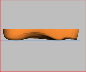
Before working with a 3D scan, you must first align the measurement with the zero line. To do this, select "Measurement" (see Figure 18), the 3D measurement is displayed. Switch to the view "I" or "A" to move the measurement with the arrow buttons (see below) so that it touches or slightly intersects the zero line (horizontal line) (see Figure 19). If the measurement is not on the zero line, the insert is pulled from the zero line to the measurement, which leads to the formation of a step in the insert.
Also check the position of the measurement in the "V" and "H". If the measurement does not correspond to the angle of attack, adjust the measurement accordingly using the arrow buttons.
| Key combination | Movement |
| Left/right arrow keys | Raise/lower the measurement left/right |
| Arrow keys up/down | Raise/lower the entire measurement |
| Ctrl + left/right arrow keys | Rotate the measurement to the left/right |
You can switch at any time between the "Insert" and "Measurement" view by selecting the corresponding option. In the view "Insert" to see the insert. Click on "Measurement", the 3D measurement is displayed.
By switching between the two views, you can get an idea of how well the insert fits the measurement data.
3.5.3.2.Toe box selection box
If this option is selected, the toe bridge of the measurement is adopted with the specified height (in mm). If the option is not selected, the insole remains flat in the toe area.
When activated, the toe bridge is inserted in such a way that the free area behind the toes is filled. By reducing the height, the toe bridge is removed from above.
3.5.3.4.Edge processing
There are two ways to edit the edge of the insert. Either use the input fields with height values (in mm) to edit the edge or use the option to edit the edge with the mouse.
Editing the border with the height values
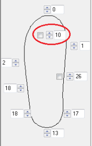
You can model the edge of the insole higher/lower by changing the height values in the input fields. Please note that you do not use the input field for the toe bridge (see Figure 22).
Note: When modelling the heel cup, it generally makes sense to edit the four rear values (marked in green). The easiest way to do this is to select the top left-hand value and enter the desired height using the keyboard. Use the Tab key to jump to the next field. Once you have changed the heights, press the Enter key and the new margin will be calculated.
You can also change the values using the arrow buttons, in which case changes to the border are calculated immediately
| Key combinationAmendment | |
| Figures | Enter the new edge height |
| Tab key | Next input field |
| Shift + Tab key | previous input field |
| Enter button | Adopting the changed edge heights |
Editing with the "Border editing" selection box
If you activate this option, you can use the standard views "I" and "A" to model the border with the mouse. To do this, click with Ctrl + left mouse button on one of the border points (coloured squares) and drag the border to the desired height.
Attention: To be able to use this option, you must be in the "Insert" (see 3.5.3.1 Insert / measurement).
3.5.3.5.Scope of action
The effective range specifies how far into the insert surface (in mm) is smoothed. The value applies to the entire edge from bale (inside) to bale (outside).
3.5.3.6.Take over
If the insert meets your requirements, you can make the changes by clicking on this button "Take over". Using key combinations (see below) you can alternatively Measurement with edge or Measurement without edge take over.
| Key combination | Take over |
| left-click on Apply | the changes are adopted |
| Ctrl + left-click on Apply | the measurement without edge would be accepted |
| Ctrl + Shift + left-click on Apply | the measurement with edge is adopted |
3.5.3.7.Copy / digitise inserts
Transferring the measurement without a margin is particularly suitable if you want to copy an insert whose data you do not have in your library. In this case, you will need a black box to scan the old insert.
Select the measurement of the insert by pressing Ctrl + left click on the "Measurement" button. Then load any insert from the library from the standard workspace of the main window. You can now use the "3D" button and Ctrl + left click on "Take over" copy the insert.
3.5.4.Models
Models are pads, toe bridges, arches, etc. that can be positioned on the insole.
You can access the area for editing models by selecting the "Models" select.
In GP InsoleCAD A distinction is made between two types of model. On the one hand there are surface models and on the other point models. The biggest difference between the two model types is how these models can be edited and how the models are displayed in the software.
Surface models: This can be imagined as an inlay. The shape of the model can be edited using similar functions to those used to model the insert. This means that the model is changed by deforming it, as the model consists of a predefined surface.
Point models: have a fundamentally different structure. As the name suggests, these models consist of individual points. The points themselves are connected by mathematical formulae so that the model can be displayed by the software. In GP InsoleCAD the connections between the points are shown as lines.
Point models can be adapted quickly and very individually by moving the points. A large part of the actual modelling is carried out by the software and the stored formulas. At the same time, this creates very round, naturally shaped models.
- If a model is inserted, the highest point of the model is always displayed as a coloured square.
- The currently selected model can be recognised by the pink coloured dot and the yellow-orange texture with the drawn lines. For point models, if the "Moulds" also shows the points by which the model is defined in addition to the highest point.
- You can recognise point models by the fact that the points are displayed in the toolbox for a selected model. This area is empty for surface models.
3.5.4.2.Model library
Saving and loading styles from the library works in a similar way as for inserts (see 3.4.1 Library management). However, no grading tables are required.
3.5.4.3.Properties ... (from models)
To change the properties of a model, first select the model. You can then change the properties of the model in the Models workspace via "Properties ..." to customise the model.
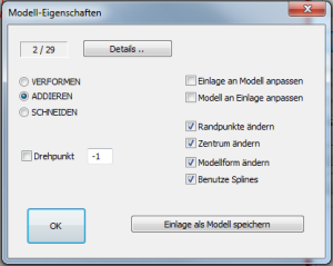
The value 2 / 29 indicates how many points the model consists of. The value cannot be changed.
Moulding: This option is obsolete and is no longer used.
Add: To be compared with gluing. The inlay is increased by the value of the model.
CuttingThe model remains on the zero line and only that part of the model which is higher than the insert influences it.
Pivot pointThis function only addresses some models from the library. This function can be used to define the centre of rotation of a CV model.
Adapt insert to modelIf you assign this property to a model and the model protrudes beyond the surface of the insert, the insert is adapted to the shape accordingly.
Adapt the model to the insoleOnly applies to special models under special circumstances.
Change edge pointsIf the check mark is set, you can change the edge points of a model.
Change centreIf the check mark is set, you can change the centre of a model.
Change model shapeIf the check mark is set, you can change the model shape/dimensions of a model.
Use splinesIf the check mark is set, the model shape is rounded. If the tick is not set, the models are sharp-edged. To illustrate this, it is best to view a model from the outside and select this property.
Note: These properties are also adopted when saving models. If you want to call up a basic model and permanently set a property, it is best to save the model again with the desired properties!
3.5.4.4.Properties Details
Some special functions of the model can be influenced via the details. These functions are not normally used and are therefore deactivated.
Among other things, models can be mirrored. When mirroring the models, ensure that they are mirrored at the coordinate origin (intersection of the bale line and foot axis).
Individual models can also be exported as STL files.
3.5.4.5.Position
To place a model, use the option "Position" in the workspace "Models" of the toolbox. Positioning is done using the following keyboard shortcuts.
| Key combination | Mouse movement | Amendment |
| Ctrl key + left mouse button | horizontal | move right/left |
| Ctrl key + left mouse button | Vertical | move up/down |
| Shift key + left mouse button | horizontal | Width/length (depending on view) |
| Shift key + left mouse button | Vertical | Height/length (depending on view) |
3.5.4.6.Moulds
NoteThis function only has an effect on point models (see 3.5.4 Models). You must be in the standard view O (top) to use this function.
You can use this function to move individual points of point models on the workspace. This function has no effect on surface models.
| Key combination | Mouse movement | Amendment |
| Ctrl key + left mouse button | horizontal | move right/left |
| Ctrl key + left mouse button | Vertical | move up/down |
3.5.4.7.Especially
You can use this function to edit any model (surface or point model). The function is identical to the function of the same name for insoles (see 3.5 3D modelling of insoles with GP InsoleCAD), but the operation is slightly different.
While holding down the left mouse button a rectangle around the area you want to change. You can then set the point of application of the deformation (green square) with Ctrl + left mouse button anywhere within the rectangle and drag with the mouse.
If you release the mouse button, you can move the point 1 millimetre in the specified direction using the V/H (front/back), I/A (inside/outside), O/U (top/bottom) buttons (see Fig. 28). Only the currently selected model is moulded. If changes smaller than 1 millimetre are required, the following key combinations are possible:
| Direction button (see Figure 28) | Changes by 1 mm |
| Shift + direction key (see Figure 28) | Minor deformations |
| Ctrl + Shift + direction key (see Figure 28) | smallest deformations |
3.5.4.8.Smooth edges
The boxes are used to smooth the edges of the model when embedding it in the inlay.
3.5.4.9.All adverts
Displays all models with a texture. However, you can still only edit a single model. You can recognise the active model as the highest point of the model is still displayed as a pink square.
3.5.4.10.Stacking
If the option is activated, the styles are "added" to each other (style, on style, on style, ...). If the option is deactivated, the models are added to the insert surface and blended with each other.
Note: If you stack models on top of each other, it is advisable to start with the smallest model, as it is then easier to re-select!
3.5.4.11.Height
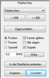
You can change the height of the activated model by entering a height in millimetres in the input field. Then click on the button "Height". The highest point of the model is adjusted to the specified height. The other dimensions of the model are retained.
NoteYou can enter both positive and negative values for the height.
3.5.4.12.Embed in the surface
Selected models are displayed after clicking on the "Embed in the surface" is integrated into the interface. When entering numbers, make sure that the English spelling is used. This means that a full stop must be used instead of a comma.
AttentionThey are then part of the surface and can no longer be changed.
3.6.Modelling of point models
As described in section 3.5.4 Models, point models can be customised by changing individual points. The boundary points can be changed by using the 3.5.4.6 Shapes option. How to adjust the slope of a point model is described below.
NoteYou can manually adjust the gradient for each line of a point model. However, it is usually better to define 4-5 lines and have the transitions between them calculated.
The two boxes in the lower section of the toolbox are used for modelling point models.
3.6.1.Lines selection box
In this box, you can mark the points of a selected point model with a simple mouse click. The rise of the line to the centre now appears in the rise view.
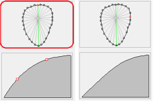
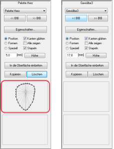
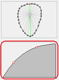
Figure 29: Left: The line selection box is outlined in red, the top point (red) is selected. The green line to the centre point is shown in the ascent view. Right: The right-hand point (red) is selected, the grey line to the centre point is shown in the ascent view. As the rise is between two green lines, it is calculated from the rise of both green lines.
By double-clicking on a point in the selection box, the grey line is coloured green and released for editing in the ascent view. Two red squares are now displayed in the ascent view. These represent points on the slope curve; the slope can be changed by moving them. The more lines you release for editing, the finer you can model your model. In practice, however, it has proven to be best to edit as few lines as possible. It is usually sufficient to edit 4-5 lines.
GP InsoleCAD calculates the rise for the grey lines between the green lines in such a way that there is a smooth transition from one modelled rise to the next modelled rise. You can see this if you mark the points between two green lines one after the other and observe the changes in the rise view.
NoteTo practise, find a point model and select a height for the model that is too high (e.g. 10 mm). You can then better observe the changes to the model in views A, I, H and V.
| Key combination | Amendment |
| Left mouse button | Select a point and view the ascent |
| left double click | Selection of a point and the ascent for editing |
3.6.3.Special function, sharp-edged models
To insert a sharp-edged model into the construction, proceed as follows.
First insert the desired model. Then enter a special character for the height, for example $, which will "destroy" the model. You can now assign the height you would like to the model (both positive and negative values). The model is then embedded with sharp edges.
3.7.Moulds
Depending on the selected shape, different modelling options are available to you. The options available to you can be found in the description of the individual shapes (see below).
As a general rule: to deform an inlay, use the keyboard (see 3.5.4.7 Special). If you use the buttons (see illustration below), the selected point of action (green square) is moved one millimetre in the selected direction.
| Direction button (see illustration above) | Changes by 1 mm |
| Shift + direction key (see illustration above) | Minor deformations |
| Ctrl + Shift + direction key (see illustration above) | smallest deformations |
While editing, you can change the model with Shift + left mouse button and a mouse movement to view the changes.
3.7.1.Sole
The sole is moulded in the selected area.
Placing the change area: The area is displayed in the "O" is released.
Setting the point of attackFree within the range with Ctrl + left mouse button.
Possible buttons: i, a, o, u, v, and h.
Free rotation with Shift + left mouse button: yes
3.7.2.Supination
In the selected area, the inlay can be turned upwards/downwards on the inside.
Placing the change area: The area is displayed in the "I" to the desired size from the front or back while holding down the left mouse button drawn.
Setting the point of attack: The point of attack is fixed.
Possible buttons: o and u.
Free rotation with Shift + left mouse buttonNo, only standard views via the buttons in the function box are possible.
3.7.3.Pronation
In the selected area, the inlay can be twisted sideways, upwards/downwards on the outside.
Placing the change area: The area is displayed in the "A" to the desired size from the front or back while holding down the left mouse button drawn.
Setting the point of attack: The point of attack is fixed.
Possible buttons: o and u.
Free rotation with Shift + left mouse buttonNo, only standard views via the buttons in the function box are possible.
3.7.4.Inside edge
The inner edge of the sole is raised or lowered in the selected area.
Placing the change area: The area is displayed in the "I" is released.
Setting the point of attackFree within the range with Ctrl + left mouse button.
Possible buttons: o and u.
Free rotation with Shift + left mouse button: yes
Attention: The function lowers/raises the entire insert up to the centre line. Excessive changes will result in a "kink" in the centre of the insert. The function should therefore only be used for changes up to a maximum of 3 mm!
3.7.5.Outer edge
The outer edge of the sole is raised or lowered in the selected area.
Placing the change area: The area is displayed in the "A" is released.
Setting the point of attackFree within the range with Ctrl + left mouse button.
Possible buttons: o and u.
Free rotation with Shift + left mouse button: yes
Attention: The function lowers/raises the entire insert up to the centre line. Excessive changes will result in a "kink" in the centre of the insert. The function should therefore only be used for changes up to a maximum of 3 mm!
3.7.6.Heel cup edge
The heel edge of the sole is raised or lowered in the selected area.
Placing the change area: The area is displayed in the "A" or "I" is released.
Setting the point of attackFree within the range with Ctrl + left mouse button.
Possible buttons: o and u.
Free rotation with Shift + left mouse button: yes
3.7.7.Heel cup total
The heel of the insole is raised or lowered to the centre in the selected area.
Placing the change area: The area is displayed in the "A" is released.
Setting the point of attackFree within the range with Ctrl + left mouse button.
Possible buttons: o and u.
Free rotation with Shift + left mouse button: yes
3.7.8.Top shell
Each click on the tip tray button adds 3 millimetres of tip edge.
3.8.Material thickness
In the Material thickness work area, the material thickness can be specified for individual areas of the insert. The specifications are in millimetres, changes are made after clicking on the "Customise" button and displayed immediately.
Note: The current values of the insert are displayed to the left of the input fields. The values are only displayed after clicking on the "Customise" has been changed. The numbers must be entered in English notation. This means that a full stop must be entered instead of a comma.
If a thickness is specified for the cover material, this value must be smaller than the smallest specified material thickness. This value is saved internally as soon as the material thickness area is exited.
3.9.Milling
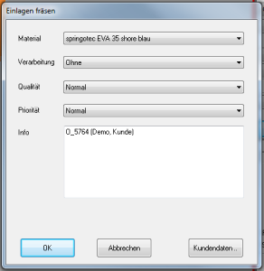
After clicking on "Milling", a dialogue box appears in which you can make additional settings (material, processing (surface), quality and priority) before producing or sending the insert data.
Once all the entries have been made in the dialogue box, the dialogue box can be closed with "OK" can be closed. A file is then created which is used for further processing by the GP Fräse programme.
Note: The entries in the list fields can be extended as required by the customer.
3.9.1.Customer data
The input of customer data is only important for GP OptiCAD if the created moulding is to be manufactured by Spenlé.
4.FAQ
4.1.How can I display an insert 1:1 on my monitor?
Make sure that the screen has been calibrated for 1:1 display. You can calibrate the screen in the GP Manager by selecting "GP Admin" -> "Calibrate screen", this is described in the GP Manager manual.
Attention: If you use different monitor models, make sure that you can only calibrate the settings for one monitor. If the monitors are not identical, it is not guaranteed that the 1:1 display is guaranteed on both monitors.
4.2.Why does an error message appear when I select "Milling"?
By clicking on the "Milling" button, the error message "The insert has negative height values! It cannot be milled!"
This error message appears if a part of the insert is below the zero line. The easiest way to rectify this error is to specify a greater material thickness for the insert. You can access these settings from the standard work area of the main window via "Material thickness". Enter larger values here so that the deposit is above the zero line.

