| 1 | Benötigte Werkzeuge: glattes, knitterfreies Papier und 7-mm-Schraubenschlüssel | ||
| 2 | Wichtige Schritte vor der Kalibrierung des Druckers: 1) Druckbett reinigen 2) Düse reinigen 3) Die Temperatur liegt unter 80 °C oder die Düse ist kalt | ||
| 3 | Legen Sie das Papier zwischen Düse und Druckbett. Prüfen Sie, ob das Papier passt. Wenn das Papier nicht zwischen Düse und Druckfläche passt, senken Sie das Druckbett durch Drücken des Abwärtspfeils (6) ab, bis das Papier passt und Sie beim Bewegen des Papiers ein leichtes Kratzen der Düse spüren. | ||
| 4 | Wenn sich das Papier frei bewegen lässt, bewegen Sie es durch Drücken des Aufwärtspfeils (8) nach oben, bis das Papier leicht an der Düse kratzt. Nachdem Sie die Kratzstelle überprüft haben, befolgen Sie die folgenden Schritte: | ||
| 5 | Aus der Position des Kratzens bewegt sich das Bett 4 Schritte nach unten, indem Sie 4 Mal auf den Abwärtspfeil drücken (6). Das Papier sollte sich nun frei bewegen können. Die Kalibrierung der Z-Höhe ist abgeschlossen. Entfernen Sie das Papier. Nun muss die Ausrichtung rechts und links überprüft werden. Drücken Sie die linke Taste (3) und prüfen Sie den Wert: Der Wert muss zwischen –0,1 und 0,1 liegen. Führen Sie die gleichen Schritte auf der rechten Seite durch. Wenn beide Werte zwischen –0,1 und 0,1 liegen, bestätigen Sie die Kalibrierung durch Anklicken des grünen Pfeils (9). Wenn die Werte nicht in diesem Bereich liegen, führen Sie die folgenden Schritte aus. | ||
| 6 | Nachdem Sie den korrekten Abstand zwischen Düse und Druckbett sichergestellt haben, justieren Sie die Bettnivellierung rechts und links, indem Sie die Federspannung unter dem Druckbett mithilfe eines 7-mm-Schlüssels durch Drehen der Schrauben (3) und (4) im Uhrzeigersinn bzw. gegen den Uhrzeigersinn anpassen. | ||
| Zum Einstellen der Nivellierung auf der linken Seite drücken Sie (3). Der Extruderkopf bewegt sich und misst die Position auf der linken Seite. Ist die Zahl größer als 0,1 (positiv), drehen Sie die Schraube mit einem 7-mm-Schraubenschlüssel langsam gegen den Uhrzeigersinn. Ist die Zahl kleiner als -0,1 (negativ), drehen Sie die Schraube mit einem 7-mm-Schraubenschlüssel langsam im Uhrzeigersinn. Drücken Sie (3), um die Position erneut zu messen. Der Wert wird angezeigt und sollte zwischen -0,1 und 0,1 liegen. Falls nicht, passen Sie die Federspannung an, bis der Wert in diesem Bereich liegt. | |||
| 7 | Um die Nivellierung auf der rechten Seite anzupassen, drücken Sie (4). Der Extruderkopf bewegt sich und misst die Position auf der rechten Seite. Ist die Zahl größer als 0,1 (positiv), drehen Sie die Schraube mit einem 7-mm-Schraubenschlüssel langsam gegen den Uhrzeigersinn. Ist die Zahl kleiner als -0,1 (negativ), drehen Sie die Schraube mit einem 7-mm-Schraubenschlüssel langsam im Uhrzeigersinn. Drücken Sie (4), um die Position erneut zu messen. Der Wert wird angezeigt und sollte zwischen -0,1 und 0,1 liegen. Falls nicht, passen Sie die Federspannung an, bis der Wert in diesem Bereich liegt. | ||
| 8 | Nachdem Sie die Nivellierung auf der rechten und linken Seite vorgenommen haben, bestätigen Sie die Kalibrierung durch Drücken des grünen Häkchens (9). Führen Sie den Kalibrierungsvorgang erneut durch, um die Werte zu überprüfen. Passen Sie die Einstellungen gegebenenfalls an. | ||
The device requires no maintenance or calibration. A metrological check is not required for commercial use.
- Disconnect the appliance from the socket before cleaning it. Do not use any liquid cleaners or sprays. Use a damp cloth for cleaning.
- The measuring surface of the device must be cleaned with a soft cloth moistened with disinfectant before or after each use.
- Only use the appliance again when it is completely dry.
- Do not expose the device to direct sunlight and protect it from dirt and moisture.
Please install the driver (XSOL) for the device before connecting the scanner to the PC via USB. It can be downloaded from our support page: gpsupport.com under Downloads/ Start/ Scanner/ GP LaserScan3D/ GT George FLAT
The power supply unit supplied is required to operate the scanner. Connect the power supply unit to the designated connection (6) on the front of the device.
The mains plug must remain accessible as it fulfils the mains disconnection function.
Do not place any objects on the mains cable. Also ensure that people do not step on the power cable or get caught in it.
 WARNING WARNING
Only use the original power supply unit for this device. The use of an unauthorised power supply unit can damage the device or be dangerous for this device. |
Please contact the manufacturer in the event of a warranty claim. If you need to send in the device, please state the defect and enclose a copy of the invoice.
The following warranty conditions apply:
- GeBioM mbH products are guaranteed for one year from the date of purchase. In the event of a warranty claim, the date of sale must be proven by the purchase receipt or invoice.
- Defects due to material or manufacturing faults will be rectified free of charge within the warranty period.
- Warranty service does not extend the warranty period, neither for the appliance nor for replaced components.
- Excluded from the guarantee are
- all damage caused by improper handling, e.g. failure to observe the instructions for use.
- Damage caused by repairs or tampering by the buyer or unauthorised third parties.
- Transport damage that has occurred on the way from the manufacturer to the consumer or during dispatch to the service centre.
- Accessories that are subject to normal wear and tear, such as batteries, sensors, etc.
- Liability for direct or indirect consequential damage caused by the device is excluded even if the damage to the device is recognised as a warranty case.
Name and model : GT George FLAT
Data transfer: USB 2.0 / USB 3.0
Laser class: 2
Connection: 1 x USB, 1 x power
Dimension: approx. 455 mm x 212 mm x 55 mm
Weight: approx. 3.2 kg
Load capacity of the measuring surface: max. 150 kg static
Measuring error: +/- 1mm
Operating conditions: +5°C to +35°C, <80 % max. rel. humidity humidity
Power supply unit: 12 V/ 3.0 A
| We reserve the right to make technical and design changes in the course of continuous product improvements. |
- The target group for this device is the specialist in the relevant field: orthopaedic (shoe) technician, engineer, biomechanist, ergonomist, etc.
- The system is therefore not intended for end users.
- In principle, the specialist should endeavour to expand and develop his or her specialist knowledge of the biomechanical relationships involved in walking, sitting and running, as the device only provides the basics and the specialist must decide personally on the measures to be taken.
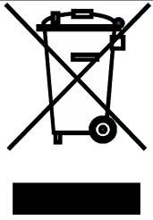 This appliance must not be disposed of with household waste. Every consumer is obliged to take all electrical or electronic devices, regardless of whether they contain harmful substances or not, to a collection point in their town or to a retailer so that they can be disposed of in an environmentally friendly manner. Please contact the manufacturer regarding disposal.
Safety instructions
|
|
Laser safety instructions
 |
|
Using the power supply unit
- Only use the original power supply unit for this device (12 V, 3.0 A). The use of an unauthorised power supply unit can damage the device or be dangerous for this device.
- Do not place any objects on the mains cable. Also ensure that people do not step on the power cable or get caught in it.
- Do not use the mains adapter if the device or the mains cable is damaged. Switch off the device and unplug the power adapter from the socket immediately.
- Never insert or remove the mains cable from the socket with wet hands.
- Disconnect the appliance from the socket before cleaning it. Do not use any liquid cleaners or sprays. Use a damp cloth for cleaning.
- Connect the mains adapter before connecting the mains cable to the mains socket.
- Unplug the mains cable from the socket before removing the mains adapter from the appliance.