Error description
The printer is not feeding any more filament or the filament has torn off.
Cause of error
The error can occur if the filament has broken inside the print head or has become stuck in the print head.
Troubleshooting
Tools required
- 1 x 7 mm open-end/lever spanner
- 1 x 16 mm open-end/lever spanner
- 1 x 2 mm Allen key
- Scissors or cutter knife
- Thermally conductive paste
- Cable ties (optional)
- Pointed pliers (optional)
- Gloves (optional)
- Heat gun (optional)
Removing the hotend from the print head
- Heat the hot end to the maximum temperature (285° - 290 °C).
It is essential to adhere to this! Otherwise the thermal barrier (heatbreak) may break! - Loosen the feed jaws and pull the filament out of the print head if necessary.
- Loosen the nozzle (open-end spanner 7 mm / 16 mm).
- Allow the printer to cool down and remove the nozzle. If the nozzle cannot be removed, heat the printer up again (285° - 290 °C) and unscrew the nozzle further.
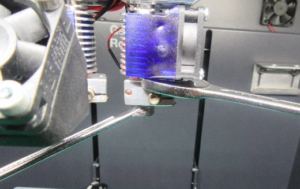
Removing the nozzle
- Loosen the lower clamping screws with a 2 mm Allen key

Loosening the clamping screws
- Disconnect all plug connections of the hotend to the wiring harness (remove the cable ties if necessary)
- Pull the hotend out downwards (turn if necessary).
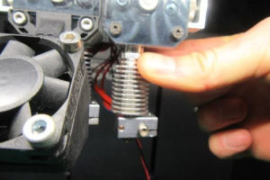
Expansion of the hotend
- Disassemble the hotend


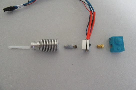
Disassembled hotend
If the parts are very dirty due to leaking filament, you can heat the parts with a heat gun and remove the soft filament.
Mounting the hotend
- Apply thermal paste to the long threaded side of the thermal barrier.
This step is important, as otherwise the filament will heat up in the heat sink and lead to a clogged hotend!

Thermal paste on hotend
- Screw the thermal barrier into the heating block until the thread is flush with the heating block.

Thermal barrier in heating block
- Screw in the nozzle by hand from the other side.
There should be a gap of approx. 1 mm between the nozzle and the heating block. If not, unscrew the thermal barrier slightly.
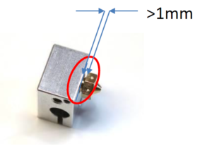
Nozzle in heating block with small gap

Mounted heating block with thermal barrier and nozzle
- TPU 93 is a very soft material that tends to bend sideways between the filament screw and Bowden. This leads to filament jams and pressure dropouts. The following solution helps to optimally guide the TPU.
Cut a piece of Teflon bowden with OD 4 mm / ID 2 mm approx. 45 mm long. Cut one end into a V-shape. This allows the hotend bowden to be pushed right up to the filament screw and the gap to be kept as small as possible.

Filament screws

Cut TPU
 Push the Teflon Bowden into the heat sink as far as it will go. The Bowden can now be moved by approx. 1 mm.
- Lift the Pushfit with a tool or your fingernail. Then push the Bowden in again as far as it will go. It should now no longer be possible to move the Bowden.


Pushfit with Bowden
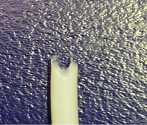
- Cut the Bowden so that it protrudes 6 mm from the hotend.

Fully assembled hotend
- Insert the hotend into the extruder with slight rotational movements and tighten the clamping screws.
Ensure that the Bowden does not touch the filament screws.

Installation of the hotend
- Reconnect all plug connections.

Connected plug connections
- Heat the hot end to 285° - 290 °C.
Important! Assembly at lower temperatures leads to sporadically clogged hotends or to parts coming loose during printing! - Tighten the nozzle against the heating block (torque 3 Nm!). Then tighten the heating block against the heat sink (7 mm and 16 mm open-end spanner).

Mounting the heating block
If all orders with the status ordered are to be displayed by default, the GP order list module must be opened, click on Ordered and then close the module using the back arrow on the right-hand side.
The programme then memorises the last selected view.
There are various options for milling on both sides. The function was originally intended for moulding beddings. However, it has also proven itself for standardised inlays.
There are a few things to consider before construction. Not all inserts can be combined with every underside.
as some would overlap with each other. Of course, the question of sense must also be asked. If a somewhat experienced employee can finish sanding the underside in 3-5 minutes, does it make any sense at all to mill customised inserts where the shape of the underside is not known?
The following options are available:
- You can create a flat underside and mill the contour or outline to make it easier to place and mark an insole as before
- You can select a suitable underside for an inlay and then mill it
- You can create a parallel or modified surface from an existing inlay and use this as the underside
Re 1:
Any insole can be selected. Once the insole has been designed, go to CAD+ and select a flat insole. This can be customised in the dimensions or you can select a suitable size. Position the insole and you're done.
Alternatively, you can also create a flat underside from the insert (by clicking on "<< Library" while holding down the Ctrl key) and then adjust its dimensions.
Re 2:
For example, you select the insert 2001101 in size 40 and the matching underside (type 6) in CAD+, also in size 40. These surfaces are matched to each other and therefore fit together. Finished.
Re 3:
You select any insert and design it. Enter a material thickness of 5 mm throughout. Then go to CAD+ and click on "<< Library" while holding down the Shift key. This creates a parallel surface that is exactly 5 mm deeper than the original surface.
Of course, you can then adjust the material thickness of the inlay, but you should leave at least 3 mm thickness depending on the material hardness. Finished.
In GpMilling, double-sided orders differ in colour. They are slightly lighter in colour. Of course, these can also be milled as normal inserts. However, if you want to mill on both sides, you must activate the checkbox for bedding and enter the exact thickness of the material to be milled. You can see the minimum thickness in the milling job overview. Select the appropriate milling scripts and create the milling files. Two files are created (einlage.ncp and einlage_unten.ncp) These can then be milled. Always start with the underside. When selecting the material, make sure that the edges are straight. Otherwise correct positioning cannot be guaranteed. The underside is positioned on the right-hand side of the milling table, the top side on the left as usual. New routers from 2011 onwards should also have been measured correctly for this function. Older models should be checked before milling for the first time.
Error description
There are inserts in the library. The inserts can be loaded from the library by name. If you open the library with the "<< Library" button, only the name of the insert is displayed, but no image.
Cause of error
The GP Manager has problems displaying the library when Windows is running with the Aero interface.
Troubleshooting
Select a display without Aero for Windows. Click with the right mouse button to an empty space on your desktop. In the following menu, select "Customise". Select a design without an aero surface.
Training video
- Introduction (0:23 min)
- Opening measurements (2:36 min)
- Axles and position (5:39 min)
- Attaching the tip (9:00 min)
- Smoothing (14:41 min)
- Dimensions (19:08 min)
- Forms (21:37 min)
- Models (23:47 min)
- Circumferential dimensions (24:42 in)
- Leg (26:35 min)
- Milling (27:27 min)
- Print (28:13 min)
Error description
The quality surcharge displayed in the GP practice/GP branch is not correct. If you enter a new price via the editor, you will be charged an incomprehensible value.
Causes of errors
To calculate the price, GP Store/GP Practice requires information from two different sources. The quality surcharge is calculated from the difference.
Troubleshooting
You can use the GP insole editor to determine the total price of the insole. The health insurance co-payment is already included in this price.
The co-payment of the health insurance company for the individual PG 08 numbers can be found in the table below. All prices are shown in the GP Manager as gross prices, i.e. including VAT of 7 %.
Example:
- The insert with the PG 08 Number 08.03.02.0 has a co-payment from the health insurance company in the amount of 69,41 € (see table below). You can see the PG 08 number in the deposit editor; this is displayed when you edit a deposit (see image "Deposit editor with PG 08 and final price").
- You would like to offer your customer a Quality surcharge of 4.06 charge €.
- This means that you must enter the following as the price in the deposit editor 73,47 € (€ 69.41 + € 4.06).

Insert editor with PG 08 and final price
If you have entered the values in this way, the invoice will be displayed as follows:

Invoice preview

Invoice printout
Example: Calculation of the gross price from the net price
If you only know the net prices for your deposits, calculate the gross price beforehand as follows:
- Net price * 1.07 = gross price
- In the example above: 68,66 * 1,07 = 73,47
At present, all health insurance companies pay the same subsidy for insoles. This subsidy is stored in a configuration file for the GP Manager. The following subsidies are currently stored in the file (as of 27/03/2020)
| PG 08 | Name | Price (€) |
|---|---|---|
| 08.03.01 | Supportive insoles | 66,88 |
| 08.03.02.0 | Bedding inserts | 78,09 |
| 08.03.02.1 | Soft upholstered bed inserts | 71,78 |
| 08.03.03.0 | Shell inserts, elasticated | 87,98 |
| 08.03.03.1 | Shell inserts, solid, mouldable | 89,73 |
| 08.03.04.0 | Three-jaw inserts | 121,83 |
| 08.03.06.0 | Shock absorber (heel cushion) | 18,05 |
| 08.03.06.1 | Shortening compensation, removable | 11,20 |
| 08.99.99.0001 | Supination/pronation wedge | 4,03 |
| 08.99.99.0002 | Heel spur recess/padding icl. leather cover | 10,56 |
| 08.99.99.0003 | Rigidus spring, incl. long leather cover | 25,96 |
| 08.99.99.0004 | Soft bedding, 4/4 - long, incl. leather cover | 11,79 |
| 08.99.99.0005 | Soft footbed, forefoot area, incl. leather cover | 6,17 |
| 08.99.99.0008 | Shortening compensation, firmly connected to the insole | 5,97 |
Error description
If you try to start a pressure measurement with GP MobilData by clicking onto the "Measure" button the dialogue opens. Afterwards the GP Manager does not respond anymore and has to be restarted.
Cause of error
The GP Manager needs a connection to the actual insoles. Each insole has a small chip with information needed for the measurement. If the GP Manager has a connection to the senders, but not to the insoles, it tires to load this information and waits for a response.
Solution
Please make sure that:
- the insoles are connected to the senders.
- the plug is connected correctly, you should hear a click.
- the insoles are connected to the right sender (L with L and R with R).
If this did'nt solve the problem please contact the GeBioM mbH support.
Error description
If you start a pressure measurement with MobilData by clicking on "Trade fairs" opens the measurement dialogue. The GP Manager then stops responding and must be closed.
Causes of errors
The GP Manager requires a connection to the measuring soles. These contain information that is required for the measurement. If the GP Manager only has a connection to the transmitters but not to the soles, it attempts to load this information and waits for a response.
Troubleshooting
Make sure that:
- the soles are connected to the transmitters.
- the soles are correctly engaged.
- the soles are connected to the correct transmitter (L to L and R to R).
To rule out that the error is due to one of the soles, please test a second pair of soles. If the GP Manager then no longer crashes, one of the two soles is faulty.
If the problem persists, please contact GeBioM mbH Support.